Showing posts with label Showcase. Show all posts

Sunday, September 3, 2023

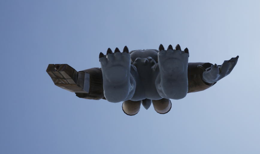
FIEA 3D Art Project #2: Minecraft-ish Level

For the second week of our 3D Art classes at FIEA, we were expected to create a Minecraft-ish level using Maya and UE5.


Tuesday, August 29, 2023

FIEA 3D Art Project #1: Rickrolling Nick with my first assignment

 For the first week of our 3D Art classes at FIEA, we were expected to create 3D sprite Art using Maya and UE5 like the reference image provided.


im sorry

Monday, August 14, 2023

Image Editor made in Unity

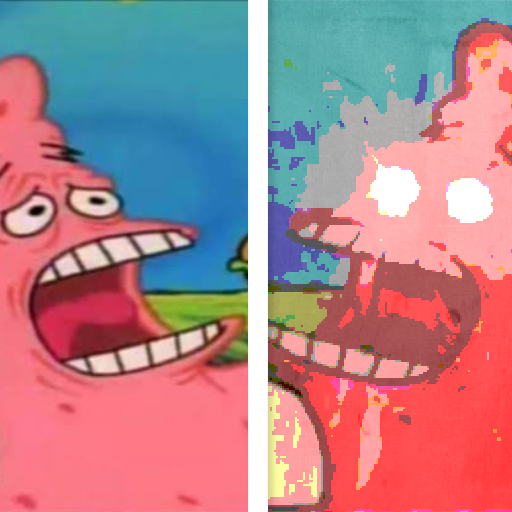
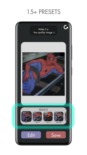
I was checking out some medium blogs to to learn some image manipulation to brush up some of my technical art skils. Them medium gods were actually pretty darn helpful and I somehow ended up developing a janky photo editor using Unity. It transforms any regular image into a “low-quality-meme”. I call it the “Low Res Meme Editor”. I’ll be discussing my approach towards developing the photo editor in this blog.


Janky Icon for a Janky Photo Editor                          The Editor UI

1.0 Preparing Images for Editing

The first step was transforming the images into a suitable format for easy manipulation. Texture2D felt appopriate for this purpose, as it gives me more control over the pixel data. I could directly manipulate pixel values using the GetPixel() and SetPixel() methods of any Texture2D object.
  • So I created method that took an image an returned a Texture2D corresponding to it.
  • Then I created an empty texture with the width and height of the image.
  • Finally the pixels on the original image are mirrored on the pixels of the empty texture using the SetPixels() method.

2.0 Image Editing Algorithms: Approach

I chose to work on a series of image editing techniques. My plan was to apply these algorithms with different settings, essentially creating pre-defined configurations for editing images. Most of these algorithms shall serve the sole purpose of giving the image a low-quality-meme look”.

2.1 Saturation Control

The first control I wished to establish was for Saturation i.e the intensity of the color of each pixel of the image.
  • A saturation value of 0 makes the image grayscale.
  • A value of 1 keeps the original colors unchanged.
  • Anything above 1 makes the image more vibrant.

Algorithm for Saturation Control
So the basic algorithm I used to achieve saturation control was–
  • Getting the texture from the image and creating an empty texture to assign the edits texture to.
originalTexture = GetTextureFromImage(image);
modifiedTexture = new Texture2D(originalTexture.width, originalTexture.height);
  • Looping through the pixels to access the HSV values from their color. The saturation value is of importance here as we are going to alter it, so it is passed as a reference type.
// accessing the texture code here

Color[] pixels = originalTexture.GetPixels();
int totalPixels = pixels.Length;

for (int i = 0; i < totalPixels; i++)
{
    Color pixelColor = pixels[index];
    Color.RGBToHSV(pixelColor, out float hue, out float saturation, out float value);    
}
  • Applying the saturation to each pixel. The saturation value is multiplied by a saturationFactor to alter it. And finally a new array of Color of length the same as the original image is assigned the color with the new saturation value.
Color[] modifiedPixels = new Color[totalPixels];

for (int i = 0; i < totalPixels; i++)
{
    // accessing HSV code here
    saturation *= _saturationFactor;
    modifiedPixels[index] = Color.HSVToRGB(hue, saturation, value);

2.2 Adding Gaussian Blur

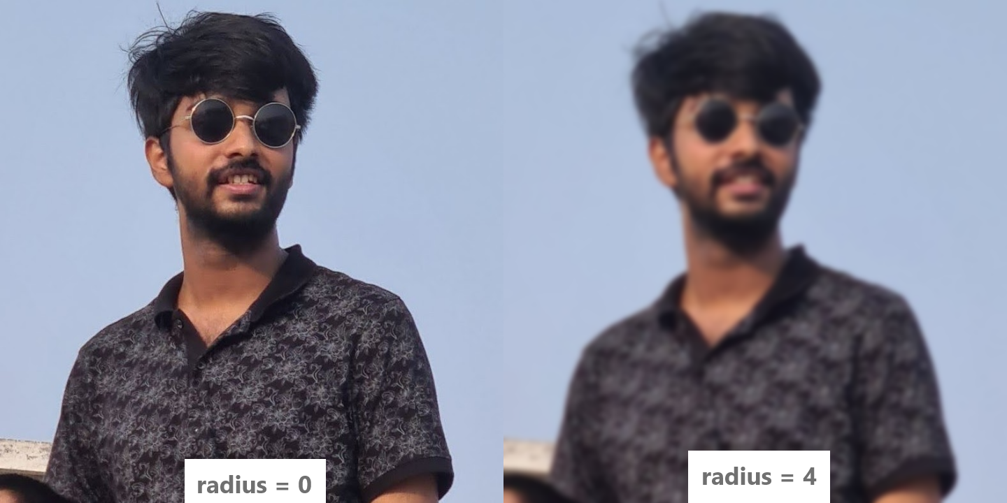
Next in the list are algorithms that helps blur an image using a Gaussian Function. This helps achieve the bokeh effect. It has the effect of reducing an image’s high frequency components and thus acting like a low-pass filter.
  • Creating the Gaussian Kernel
    • First we create a gaussian kernel of a given size and radius. The gaussian kernel is a float 2D matrix (float[,]). Each element in the matrix is a weight that determines the contribution of each pixel to the blurring process. These weights are calculated based on the Gaussian distribution formula.

    • Input Parameters: The CreateGaussianKernel() method takes the radius and size of the kernel as the parameter and returns a 2D matrix (float[,]). The size represents the dimensions of the kernel, and the radius controls the spread of the blur effect. 
         private float[,] CreateGaussianKernel(int size, float radius) {}
    • Initialization:  An empty 2D array called kernel of size x size is initialized. This array will store the weights that determine the strength of blurring for each pixel. The variable sigma is calculated as radius / 3f. sigma is a parameter that affects the spread of the Gaussian distribution. A larger sigma value results in a wider spread of the blur. The constant for the gaussian distribution is calculated as twice the sigma squared.
        float[,] kernel = new float[size, size];
        float sigma = radius / 3f; 
        float twoSigmaSquare = 2f * sigma * sigma; 
        float totalWeight = 0f; 
    • Gaussian and Total Weight Calculation:  The nested loops iterate over each element of the kernel array. For each element at position [y, x], it calculates the squared distance from the center of the kernel. The formula x * x + y * y calculates the squared Euclidean distance. Using the squared distance, it calculates the weight using the formula Mathf.Exp(-distance / twoSigmaSquare). This weight is a measure of how much influence a pixel at that distance should have on the blurring process. The greater the distance, the smaller the weight. The calculated weight is assigned to the corresponding position in the kernel array. The totalWeight variable keeps track of the sum of all the weights in the kernel. This sum is used to normalize the kernel later.
        // intialization code here

        for (int y = -size / 2; y <= size / 2; y++) // -size / 2 to size / 2
        {
            for (int x = -size / 2; x <= size / 2; x++) // -size / 2 to size / 2
            {
                float distance = x * x + y * y; 
                float weight = Mathf.Exp(-distance / twoSigmaSquare); 
                kernel[y + size / 2, x + size / 2] = weight; 
                totalWeight += weight;
            }
        }
    • Kernel Normalization:  After calculating all the weights, the kernel is normalized to ensure that the sum of all the weights equals 1. This step is essential to maintain the overall brightness of the image during blurring. The nested loops iterate over each element of the kernel array again. Each weight is divided by the totalWeight, effectively scaling down the weights to ensure their sum equals 1. And then the kernel is returned.
        // intialization code here

        // weight calculation code here

        for (int y = 0; y < size; y++)
        {
            for (int x = 0; x < size; x++)
            {
                kernel[y, x] /= totalWeight;
            }
        }

        return kernel;
  • Applying the Gaussian Kernel 
    • After calculating all the weights, the kernel is normalized to ensure that the sum of all the weights equals 1. This step is essential to maintain the overall brightness of the image during blurring. The nested loops iterate over each element of the kernel array again. Each weight is divided by the totalWeight, effectively scaling down the weights to ensure their sum equals 1. And then the kernel is returned.
    • Input Parameters: The ApplyKernel() method takes a Texture2D as input along with a kernelxy (position within the image) and size of the kernel as the parameter. It then calculates and returns the weighted average of colors in the neighborhood around the (x, y) position using the provided Gaussian kernel.
        private Color ApplyKernel(Texture2D texture, int x, int y, float[,] kernel, int size) {}
    • Input Parameters: The ApplyKernel() method takes a Texture2D as input along with a kernelxy (position within the image) and size of the kernel as the parameter. It then calculates and returns the weighted average of colors in the neighborhood around the (x, y) position using the provided Gaussian kernel. 
        float r = 0f, g = 0f, b = 0f;
        int halfSize = size / 2;
    • Looping through the Kernel: Nested for loops iterate over each cell in kernel. The outer j loop iterates over the rows of the kernel whereas the inner i loop iterates over its columns.
        for (int j = 0; j < size; j++)
        {
            for (int i = 0; i < size; i++)
            {
        
            }    
        }
    • Retrieving and Updating the color values of pixels The color values of pixels at calculated coordinates offsetX and offsetY are retrieved from the input texture. The RGB values intialized earlier are updated by adding the color values retrieved multiplied by the weight value from the Gaussian Kernel matrix from the i and j position. The final color obtained is returned.
        Color pixel = texture.GetPixel(offsetX, offsetY);
        float weight = kernel[j, i];

        r += pixel.r * weight;
        g += pixel.g * weight;
        b += pixel.b * weight;
  • Applying the Gaussian Blur:  Now we apply the gaussian blur to the image by calculating the kernel, processing the pixel and updating the image.
    • Input Parameters: The ApplyGaussianBlur() method takes a Texture2D as input along with the radius of the Gaussian Blur needed (basically used as the size of the kernel) and returns the blurred texture.
        private Texture2D ApplyGaussianBlur(Texture2D sourceTexture, float radius) {}
    • Calculating Kernel size and Kernel: The Kernel size is obtained by rounding the radius to the nearest integer, doubling it and then adding 1 to it, ensuring coverage of sufficient area around each pixel.
        int kernelSize = Mathf.RoundToInt(radius) * 2 + 1;
        float[,] kernel = CreateGaussianKernel(kernelSize, radius);
    • Creating Blurred Texture: A new blurredTexture with same dimensions as sourceTexture is initialized.
        Color[] pixels = sourceTexture.GetPixels();
        Color[] blurredPixels = new Color[pixels.Length];
    • Iterating through pixels: A nested loop is used to access the pixels of the sourceTexture. For each pixel at (xy), the ApplyKernel() function is called to calculate the new color of that pixel. The calculated blurrer color is stored in the corresponding position of the blurredPixels array.
        for (int y = 0; y < sourceTexture.height; y++)
        {
            for (int x = 0; x < sourceTexture.width; x++)
            {
                Color blurredColor = ApplyKernel(sourceTexture, x, y, kernel, kernelSize);
                blurredPixels[y * sourceTexture.width + x] = blurredColor;
            }
        }
    • Applying Blurred pixels to the Texture: After processing all the pixels, the blurredPixels array is assigned to the blurredTexture and it is returned.
        blurredTexture.SetPixels(blurredPixels);
        blurredTexture.Apply();

        return blurredTexture;
    • Blurred Sprite: A sprite is created from the blurred texture and is applied to the image.
        Sprite blurredSprite = Sprite.Create(blurredTexture,
                                    new Rect(0, 0, blurredTexture.width, blurredTexture.height),
                                    new Vector2(0.5f, 0.5f));
        image.sprite = blurredSprite;

**Still in works**

Monday, July 25, 2022

Work at FIEA (Summer Internship) - Documented!

I did a remote internship with people from FIEA last summer before actually joining its Master's program. I assisted the very talented  19 Souls on Board team in their capstone project Soul Shard --  a cooperative puzzle platformer that draws inspiration from EA’s ‘It Takes Two’. The repository containing my contributions to the project can be found here.               

   Soul Shard Poster                             19 Souls on Board Logo

1.0 Smoke System

My first task was to design and develop a stylized explosive smoke particles for various machinery and explosions in the game. The basic idea was to develop a functional prototype and then refine it in the iterative design process.

1.1 Cloud Texture

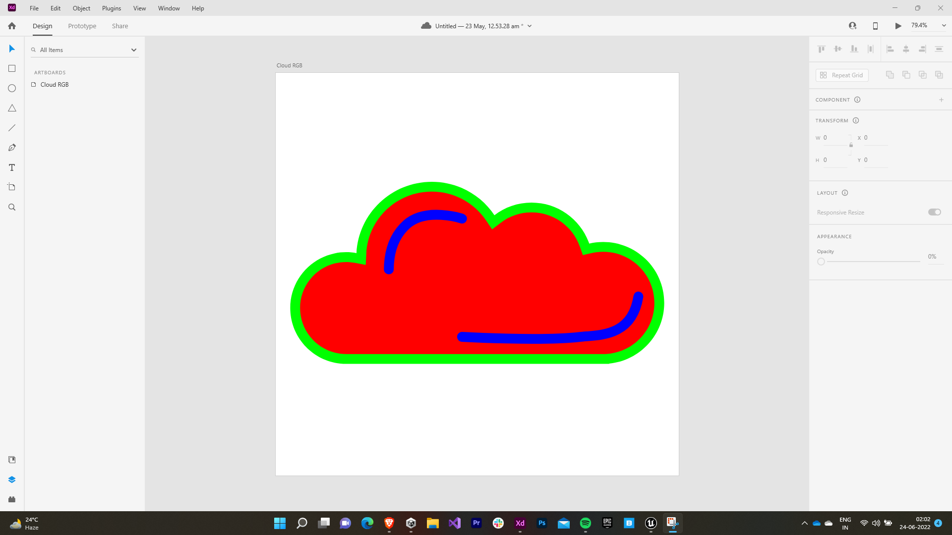
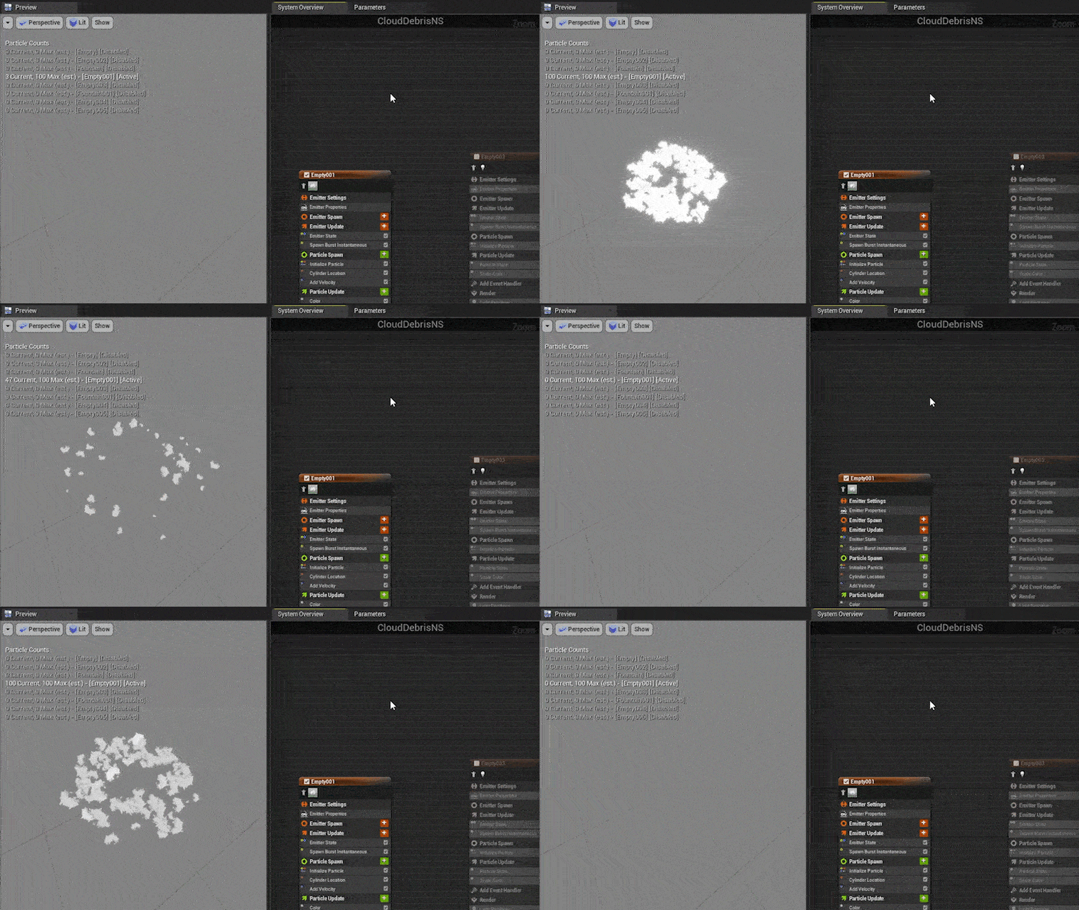
Initially, I designed various cloud textures with separate RGB channels for Base Color, Emmisivity and Opacity Mask.


1.2 Smoke Material

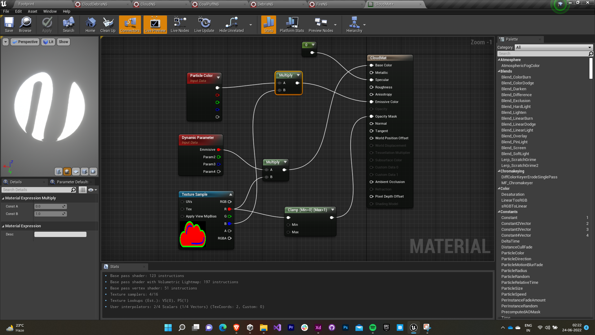
  • The smoke material was made using these textures.
  • The emissivity and particle colors were exposed for editing while making the particles.

1.3 Smoke Particles - 1st iteration

  • The smoke particles were made using the Niagara VFX system.
  • The particles (100) were made to spawn in a burst around a cylinder with an initial velocity radially outwards.
  • A positive gravitational force was added to make the particles rise with a drag coefficient to smoothen things and make it feel natural.
  • Individual particles also received rotation in addition to a colour (the exposed parameter) that was lerped from grey to black.
    

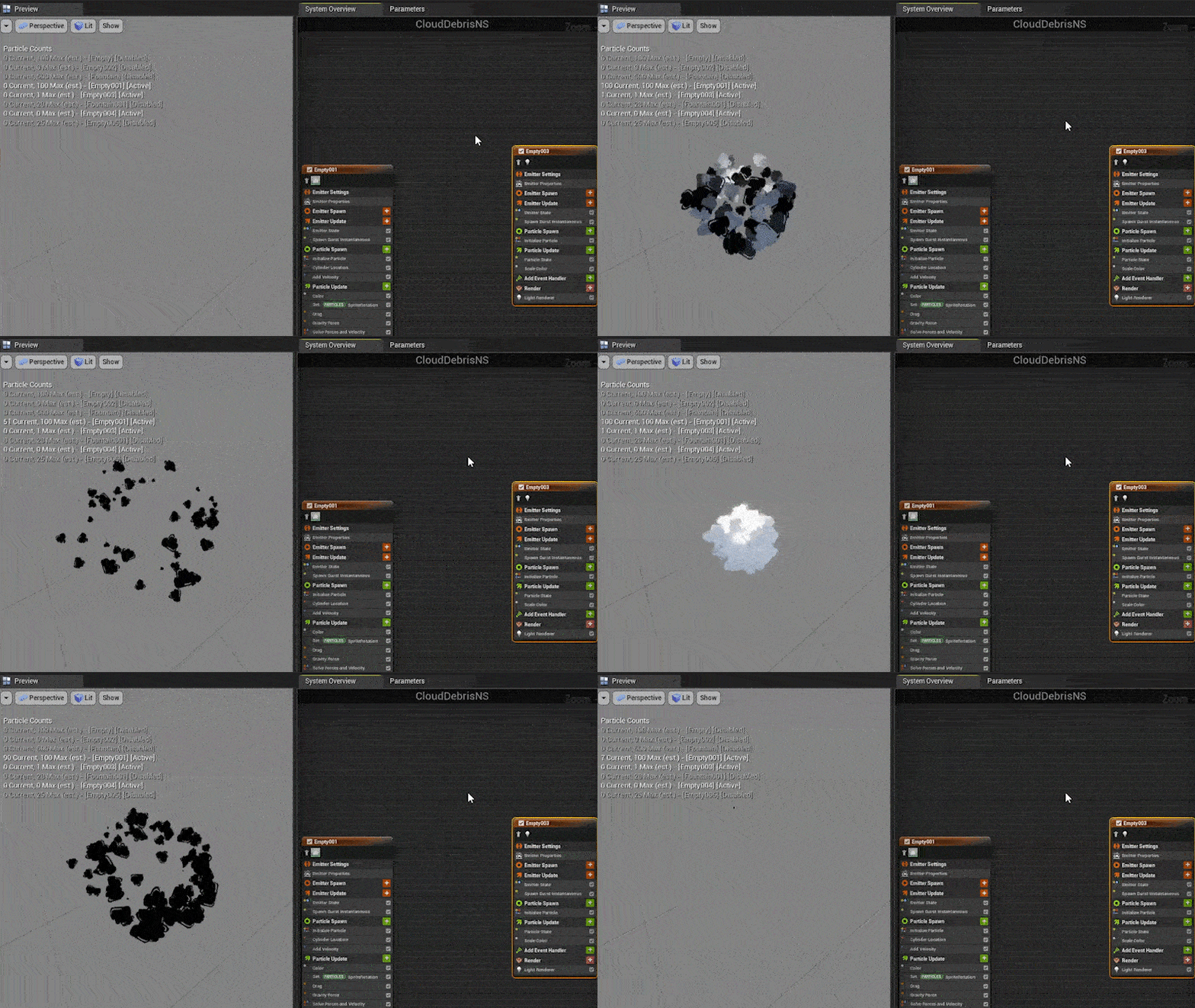
1.4 Smoke Particles - 2nd iteration

  • A light renderer was added to the particles to further intricately define the explosion.
  • The light renderer was started off at the same initial position as the smoke particles.
  • The intensity was lerped from 100 to 0.

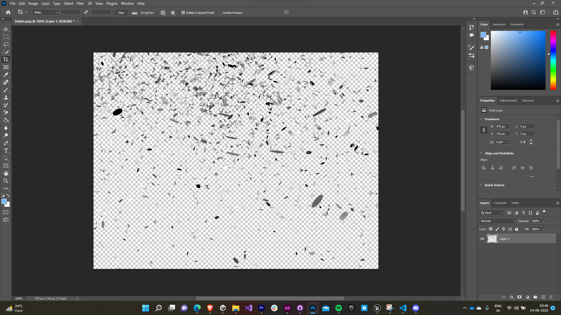
1.5 Debris Texture

The debris texture was made in photoshop using online reference images and the brush tool.


1.6 Debris Material

The debris material was created using the debris texture in a similar fashion to the smoke material.


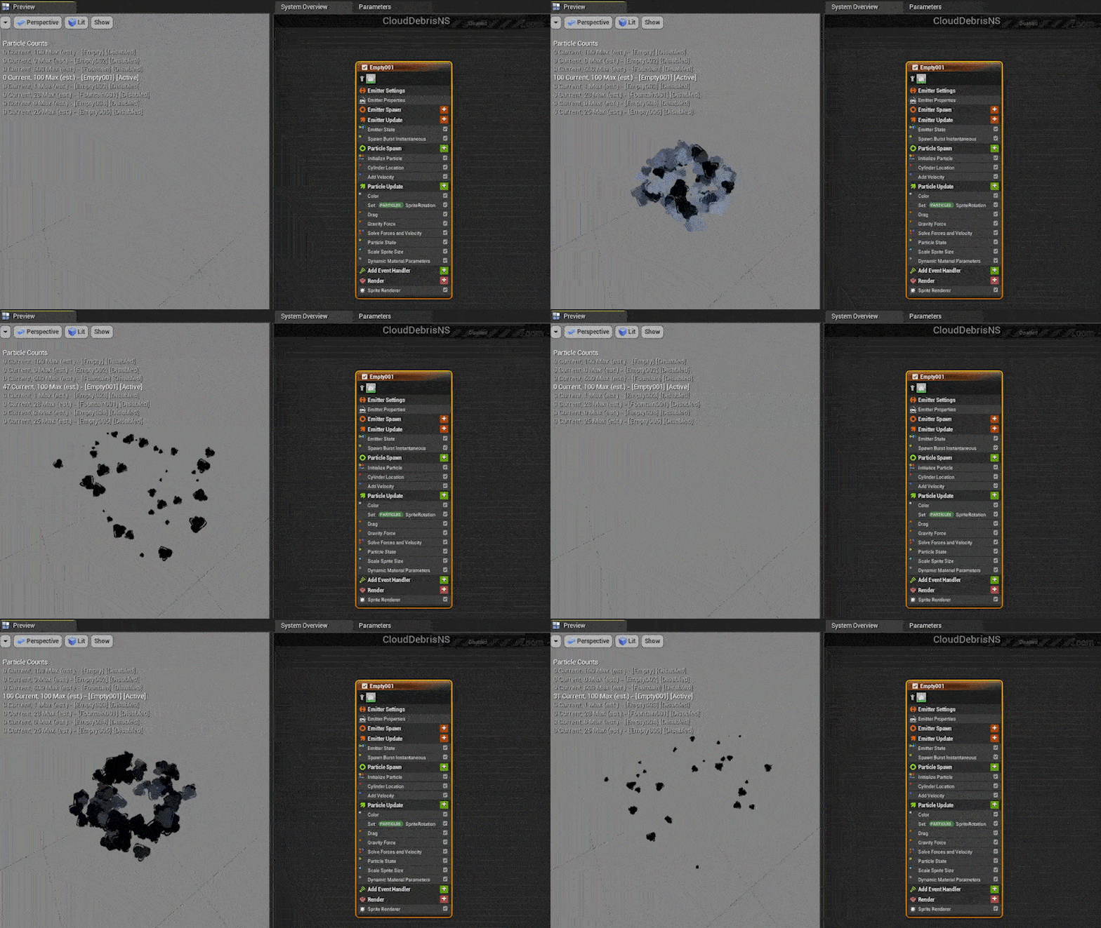
1.7 Smoke Particles - 3rd iteration

  • The debris particle was given the same parameters as the smoke particle.
  • Since the debris appeared lighter, the drag was reduced and gravitational force (positive) was raised to increase the spread.
  • Apart from that, a fountain emitter was assigned the same debris material to make the spread look more abrupt.


1.8 Spark Texture

The spark texture with separate RGB channels was obtained online.

1.9 Spark Material

  • The spark material was made using the spark texture.
  • The blue channel was used as the opacity mask.
  • The emissive color was obtained after combining red and yellow.

1.10 Smoke Particles - Final iteration

The spark particles were given the same parameter as the debris particle, i.e. a higher spread emitter and a fountain emitter.

1.11 Other Variations

Few other variations of the smoke system.
Less stylized system                      Debris only system         


Puff system

2.0 Flame system

My subsequent task was to design & develop flame systems for different purposes like burning coal, chimneys, explosion, etc.

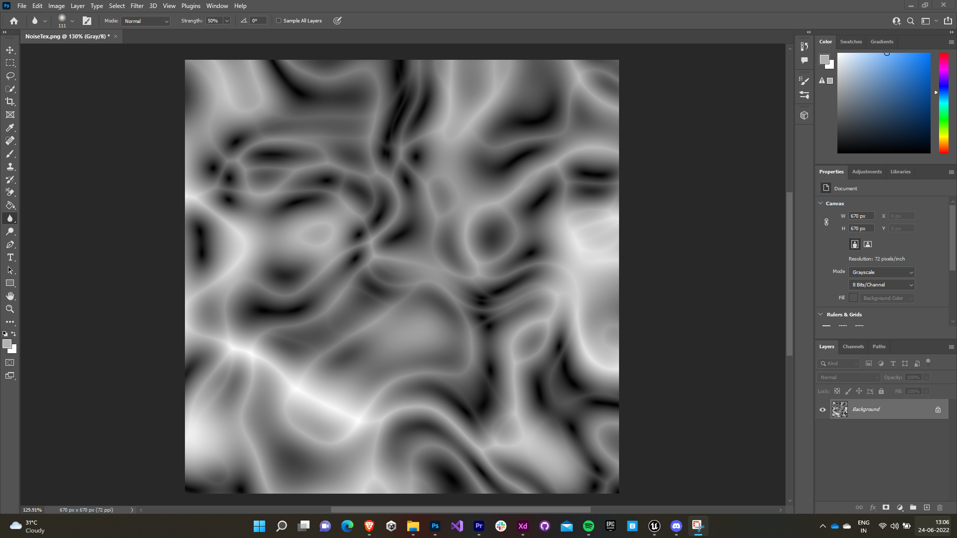
2.1 Noise Texture

A stylized noise texture was created to serve as the opacity mask for the flame material.

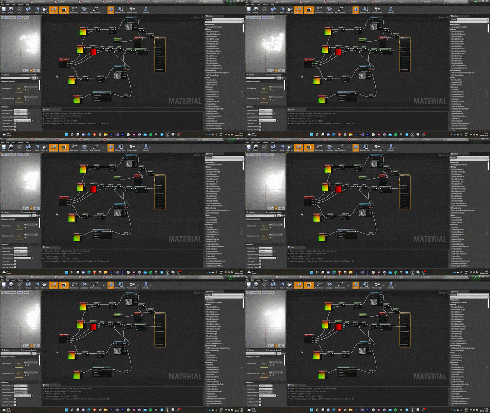
2.2 Flame Material

  • Parametrically controlled texture coordinate was masked to obtain a controllable gradient. The value is clamped between 0 and 1 to prevent excessive bleeding.
  • The noise texture was added to give fire-like shape to the mask.
  • The UV map of the texture was given a panner (with texture coordinate as input) to animate it, depicting a burning fire.
  • A RadialGradientExponential (with texture coordinate as input) was subtracted from the mask to prevent square edges.
  • The tiling, erosion & color of the material were exposed as dynamic parameters to be controlled by the Niagara system.

2.3 Flame Particles - 1st iteration

  • Majorly, the structure of flame system was completed during the formation of material itself.
  • The sprites were spawned in a circular grid with different rotations to give a 3D look.
  • The color was lerped between yellow and red.

2.4 Flame mesh

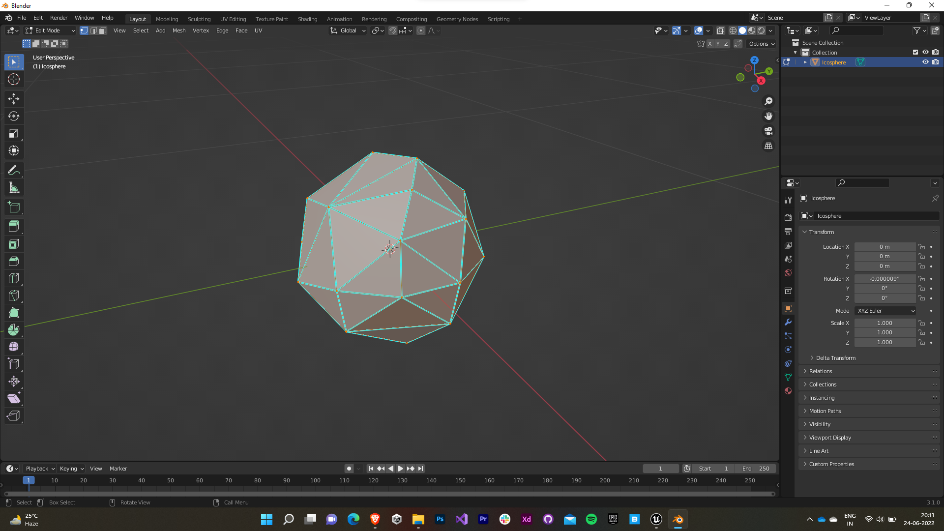
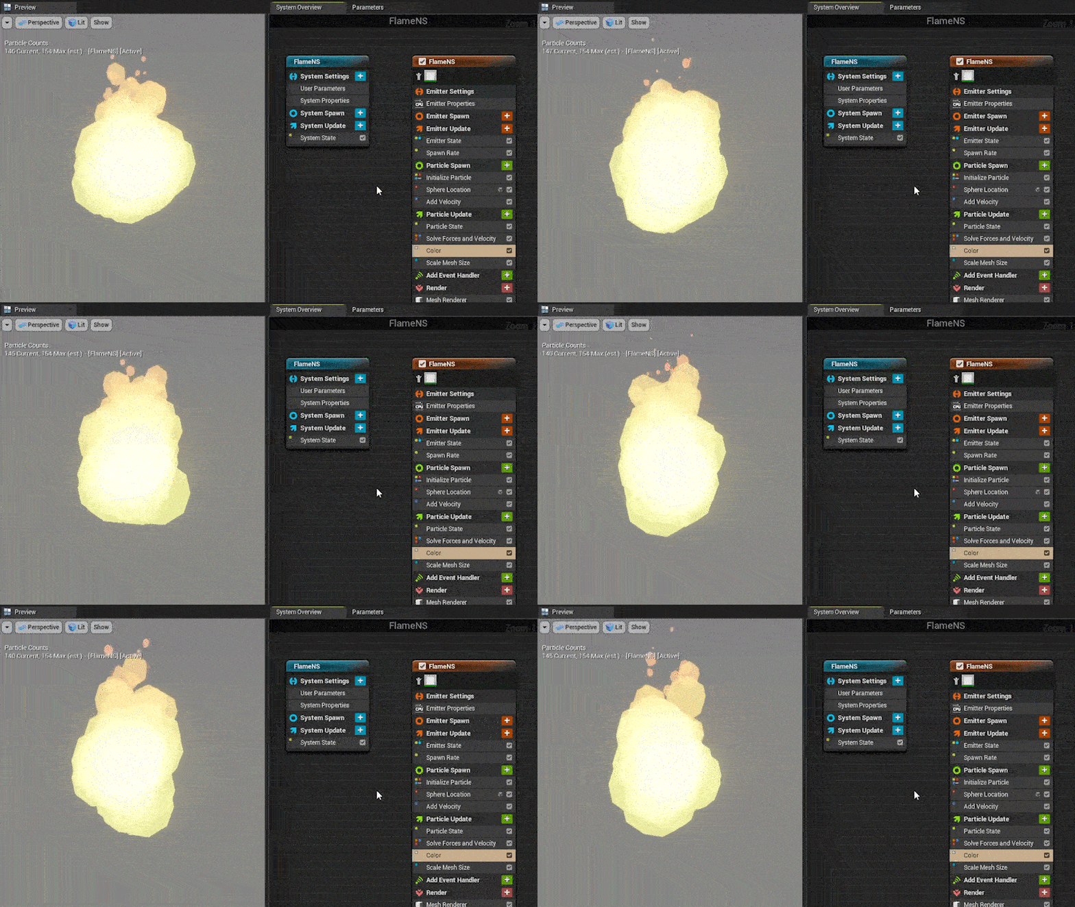
The flame system previously made was disapproved by the team for being too toony and not matching the game tone setting. So I decided to replace the sprite based particle system to a mesh one. I modeled an icoshpere mesh with decimate modifier for this purpose to provide randomness.

2.5 Flame material

The flame material was created simply by assigning the particle color input to the emissive color of the material so that we can assign it later in the emitter itself.

2.6 Flame Particles - Final iteration

  • A fountain based emitter is used after removing gravity, cone velocity, drag and scaleColor just retaining the initial properties.
  • The default sprite renderer is replaced with a mesh renderer and the icosphere and the flame material we created is assigned.
  • The particles were assigned a random vertical velocity so that variance in the fire’s peak giving it a natural eye.
  • They’re scaled down in size as they reach up to give an inverted conical shape by using bezier curves to keep the transition smooth.
  • The color is lerped between yellow and red with the lifetime of the particle.

3.0 Footprint System

Further I was assigned the task to develop a snow-based footprint system over snow for the main characters (Ambrose and Nimue).

3.1 Footprint Sprites - 1st iteration

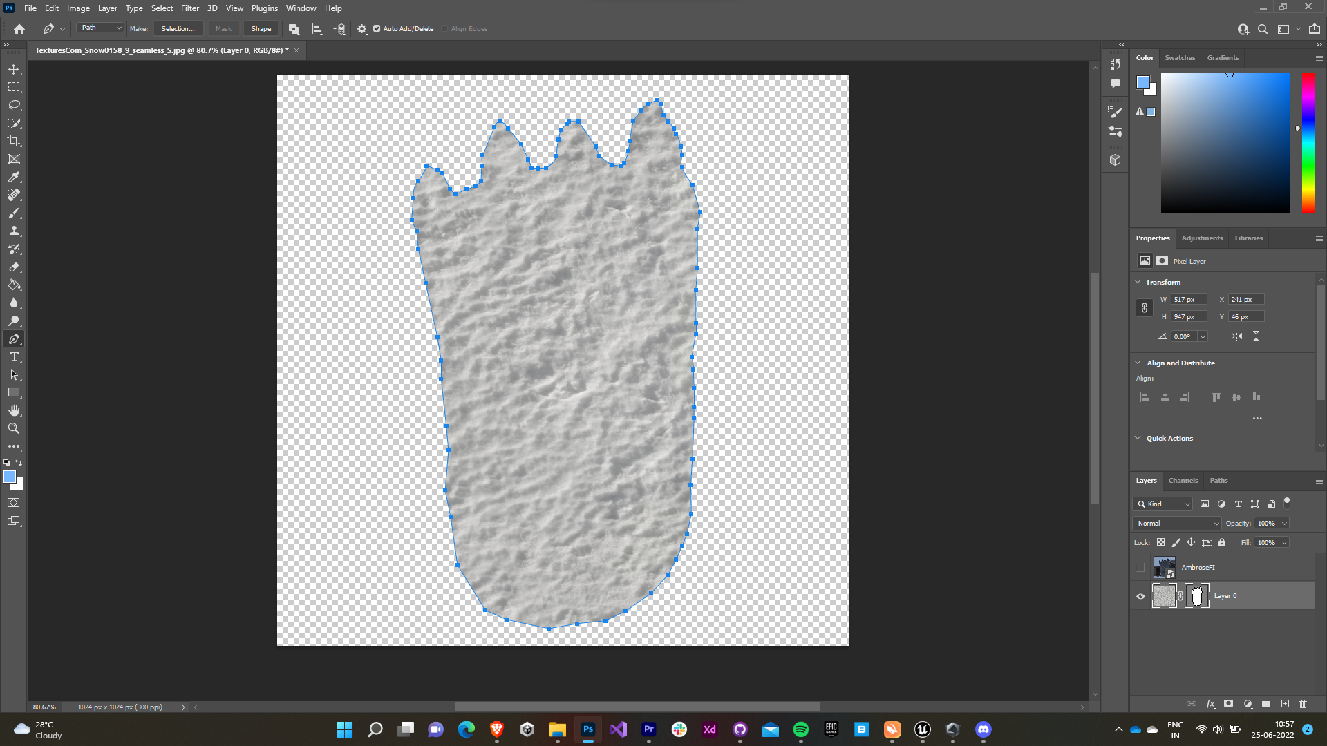
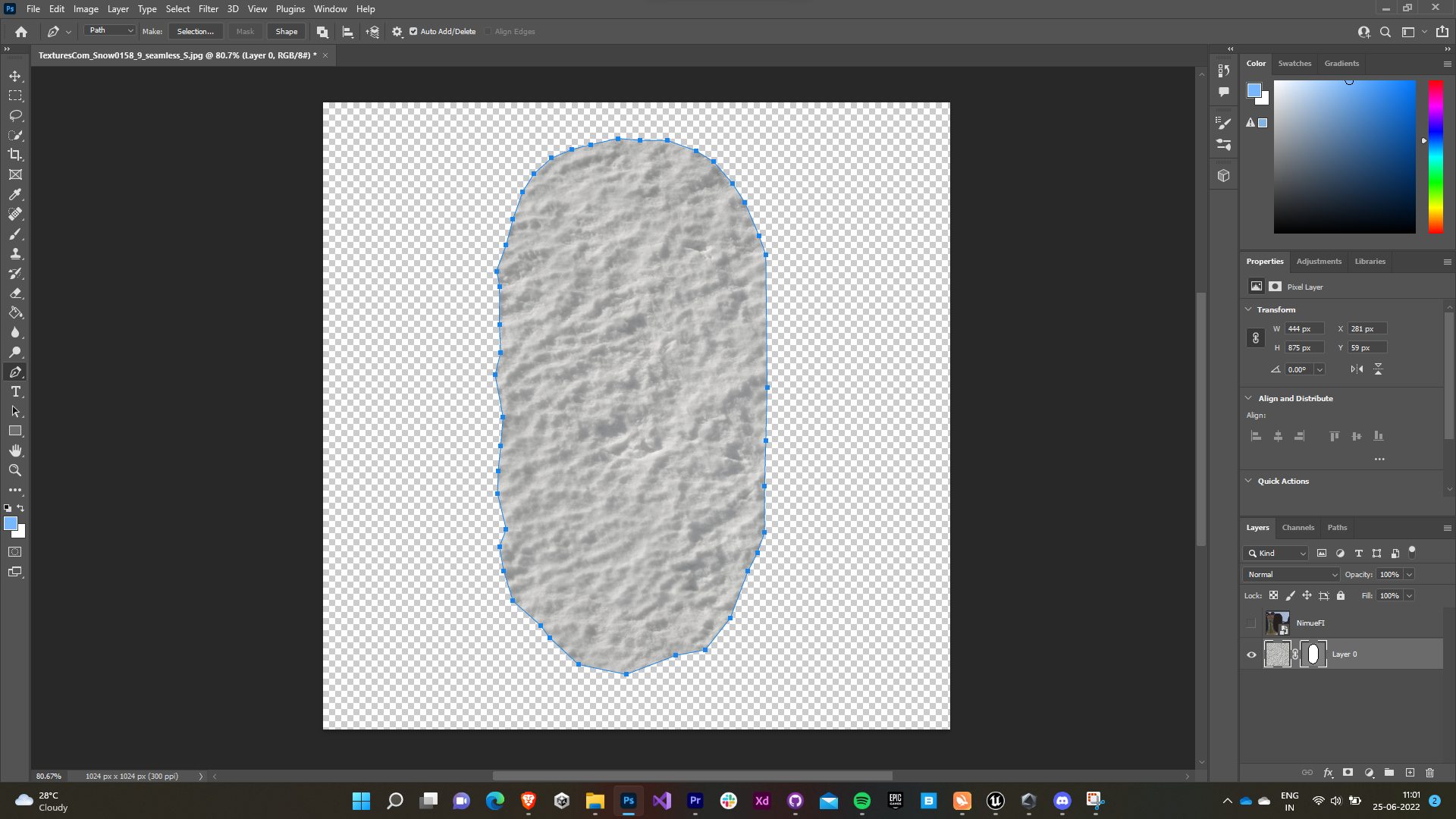
  • I used a snow texture which I found online to make the footprint sprites.
  • The foot impressions of the right foot of both the characters were traced using the pen tool and the texture was masked to make the footprint sprites.
  • The left footprint sprite was simply made by inverting the image horizontally.
Ambrose Foot Impression            Nimue Foot Impression
   Ambrose Footprint Sprite            Nimue Footprint Sprite

3.2 Footprint Material - 1st iteration

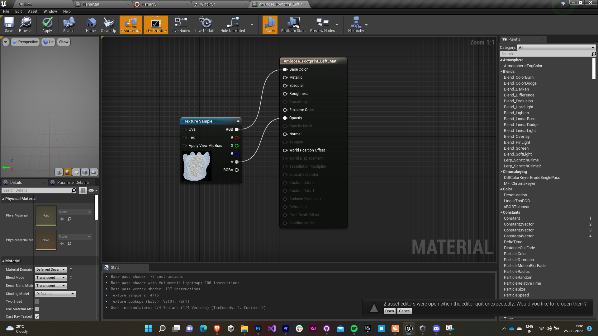
  • The material used for the footprints was a deferred decal material with blending mode set to translucent so that you can apply it as a decal.
  • The alpha of the texture/sprite was assigned to the opacity of the material and the RGB values to the base color.

3.3 Footprint Blueprint

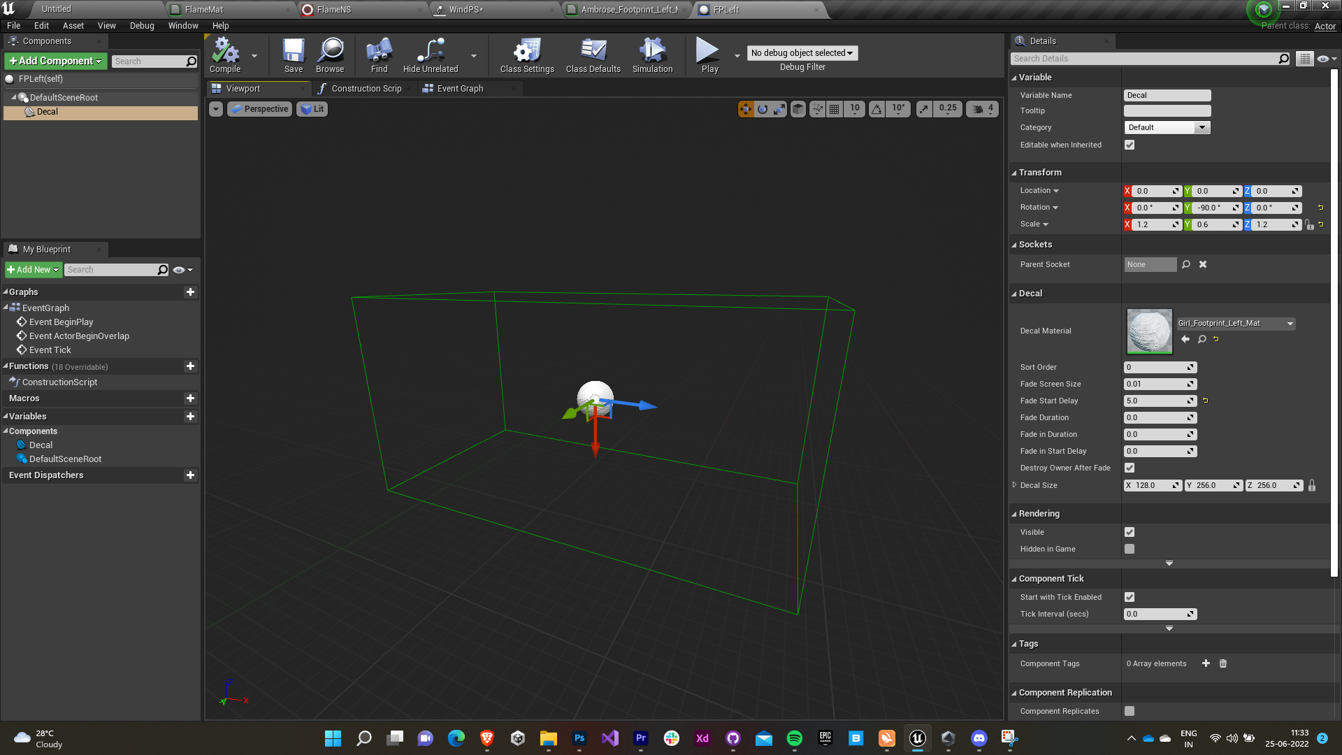
  • An actor blueprint is created for both left and right footprints.
  • A decal facing downwards with the footprint material is added as the child to the DefaultSceneRoot.
  • The decal is made to fade away gradually after 5 seconds.

3.4 Adding to the third person blueprint

  • I used the default third person character provided by Unreal to playtest the footprints.
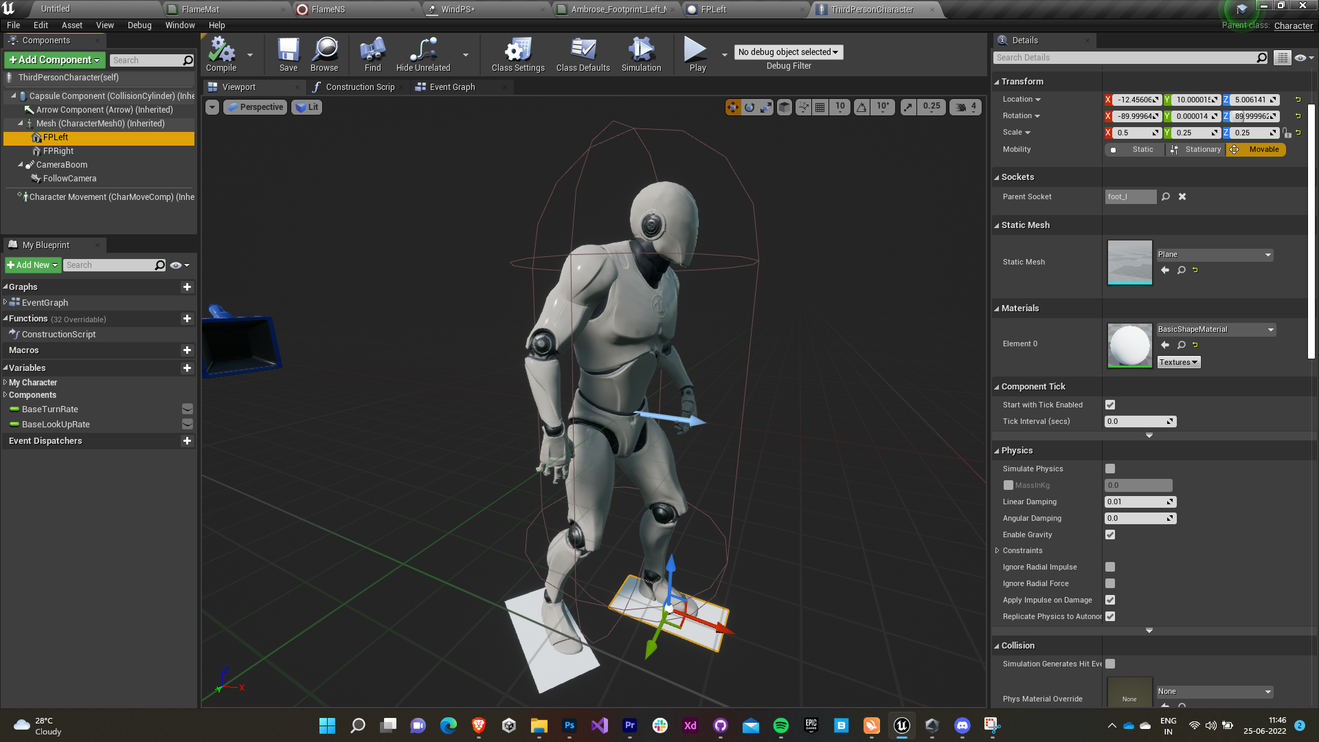
  • In the TPC blueprint, planes are added as a child of the mesh and the respective foot as the parent socket so that it snaps perfectly with the foot’s movement.
  • The planes are rendered as invisible (hidden in game), events are prevented from overlapping, and collisions are disabled as they’re just meant for spawn reference to the footprints.

3.5 Animation Notifier 

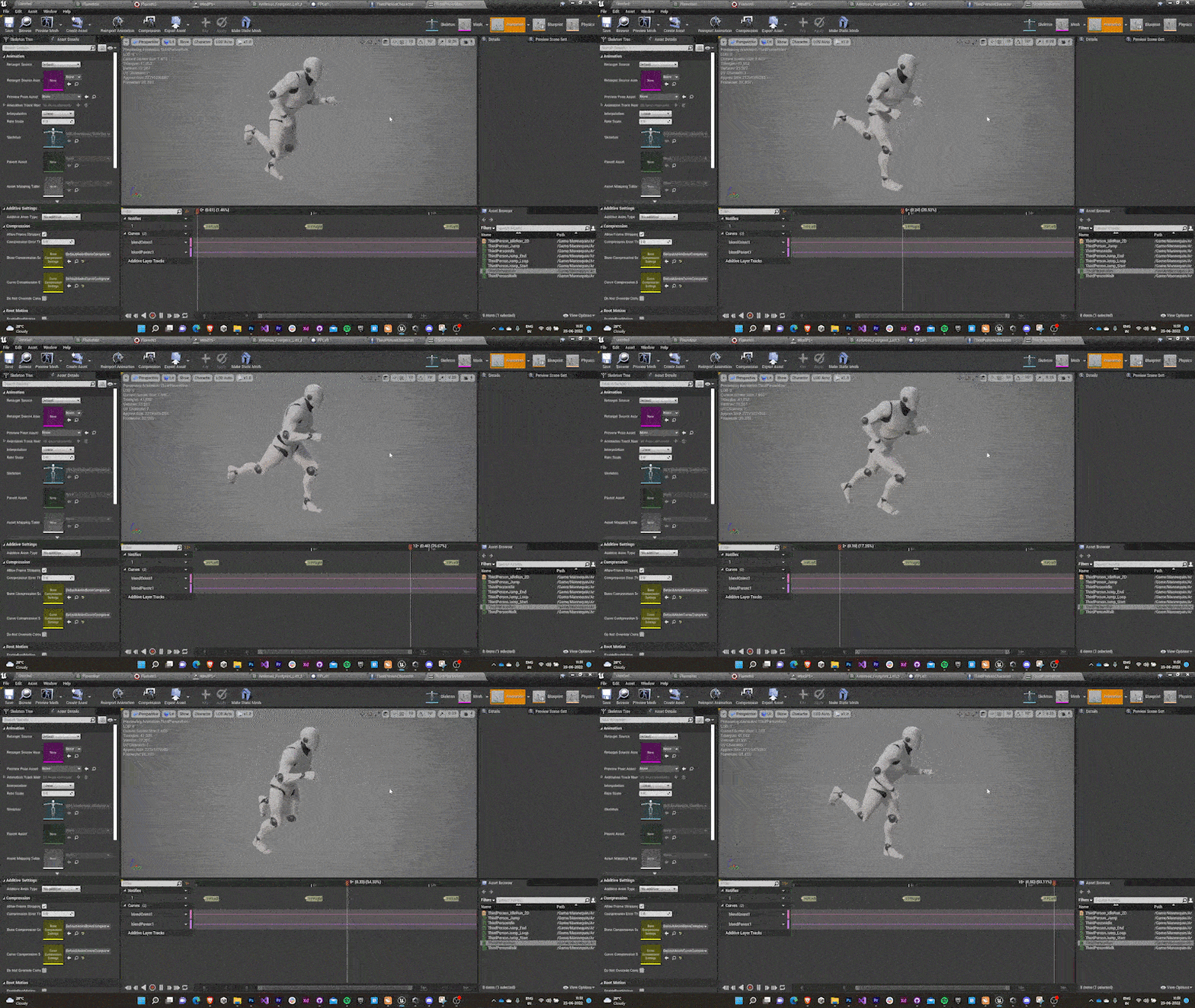
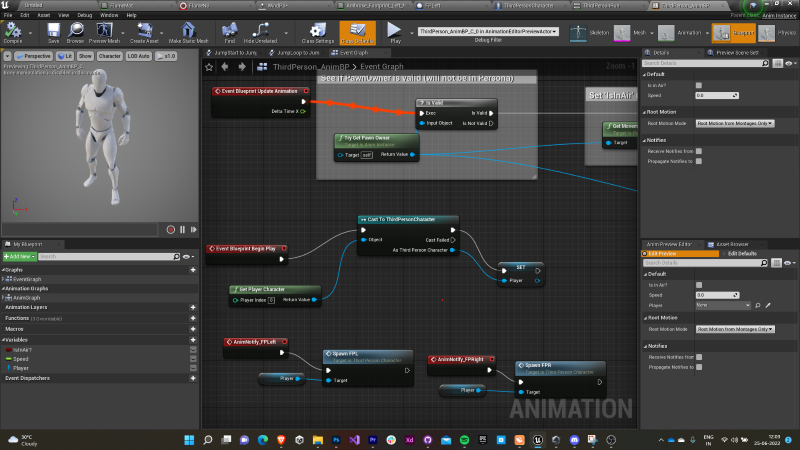
  • Animation notifiers are added for each footprint to spawn at the appropriate time in the running animation.
  • In the third person animation blueprint’s event graph, a character reference is set and cast to the third person character as the blueprint awakes.
  • In the third person character blueprint’s event graph, two new custom events are introduced to spawn the footprints.
  • The event is meant to spawn an actor from the footprint class we created earlier.
  • The foot reference is assigned to the spawn location.
  • The actor rotation is assigned to the spawn rotation.
  • The spawn scale was decided after playtesting.
  • The custom events are assigned to the animation notifier in the third person animation blueprint’s event graph.

Adding run animation notifier


Third person animation event graph


Third person character event graph


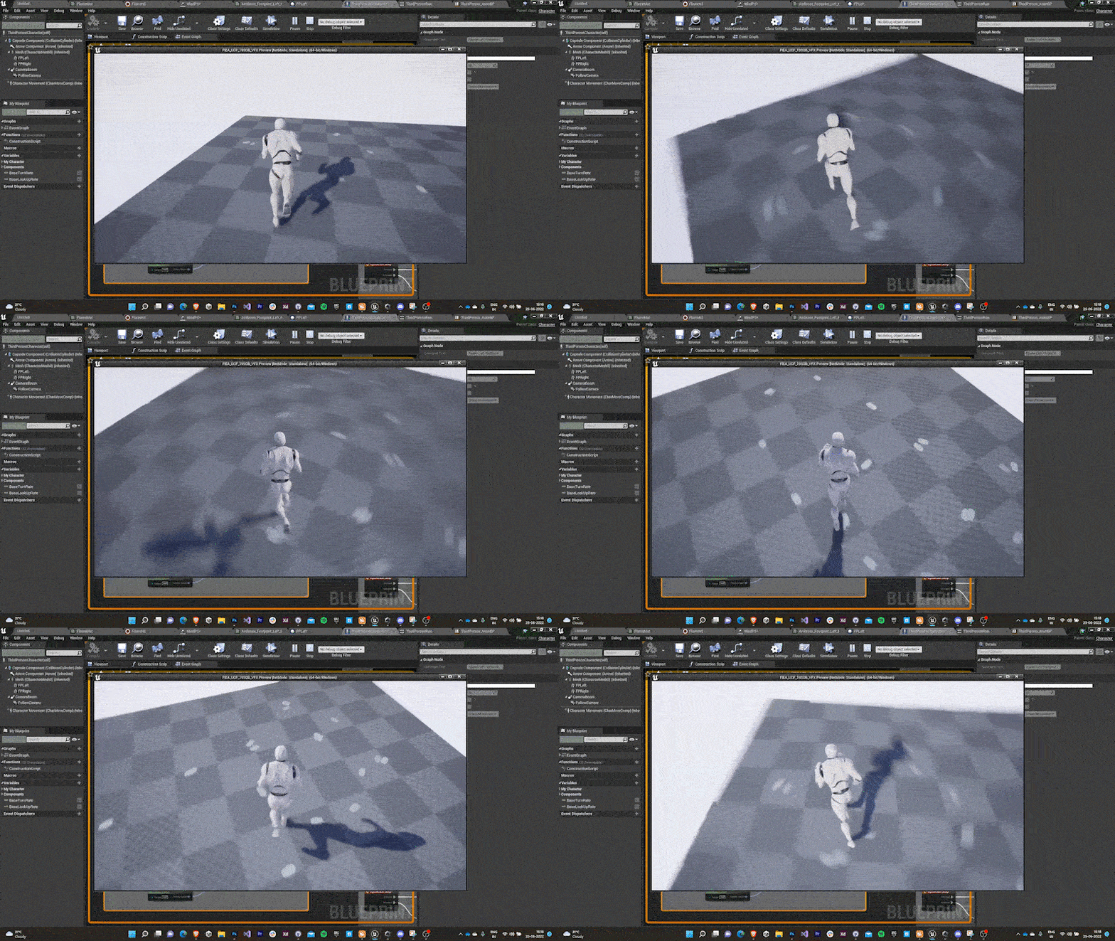
First Output

3.6 Footprint Sprites - Final iteration

    The team pinpointed that the current footprint lacked originality as snow footprints are generally a little darker (dark grey/blue) with blue tint on the edges. Apart from this, they suggested to add normal information to the footprints as well.

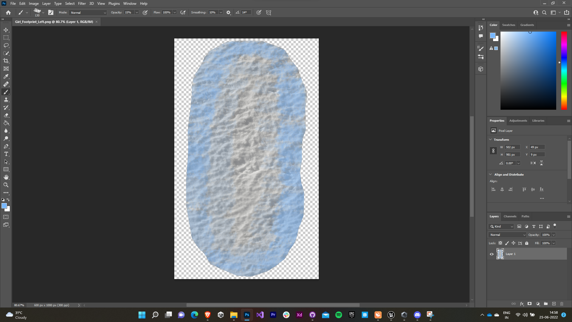
    • I decreased the exposure of the textures, added bluish tint on the edges using the brush (Chalk 2) tool.
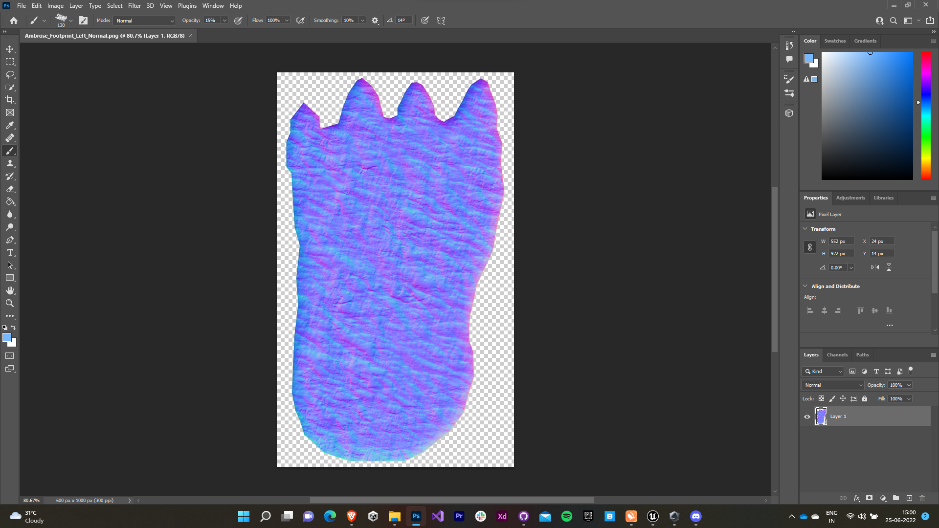
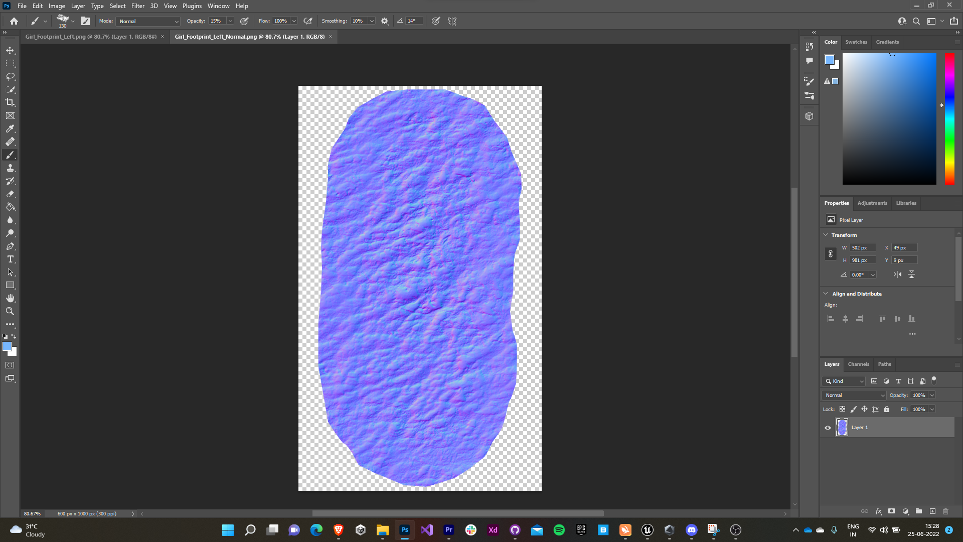
    • Further, I generated the normals using the inbuilt 3D tools provided in Photoshop. (which turned out to be one of my most laggy workflow experiences with Photoshop).
    New Ambrose Footprint Texture         New Nimue Footprint Texture
     Ambrose Footprint Normal            Nimue Footprint Normal

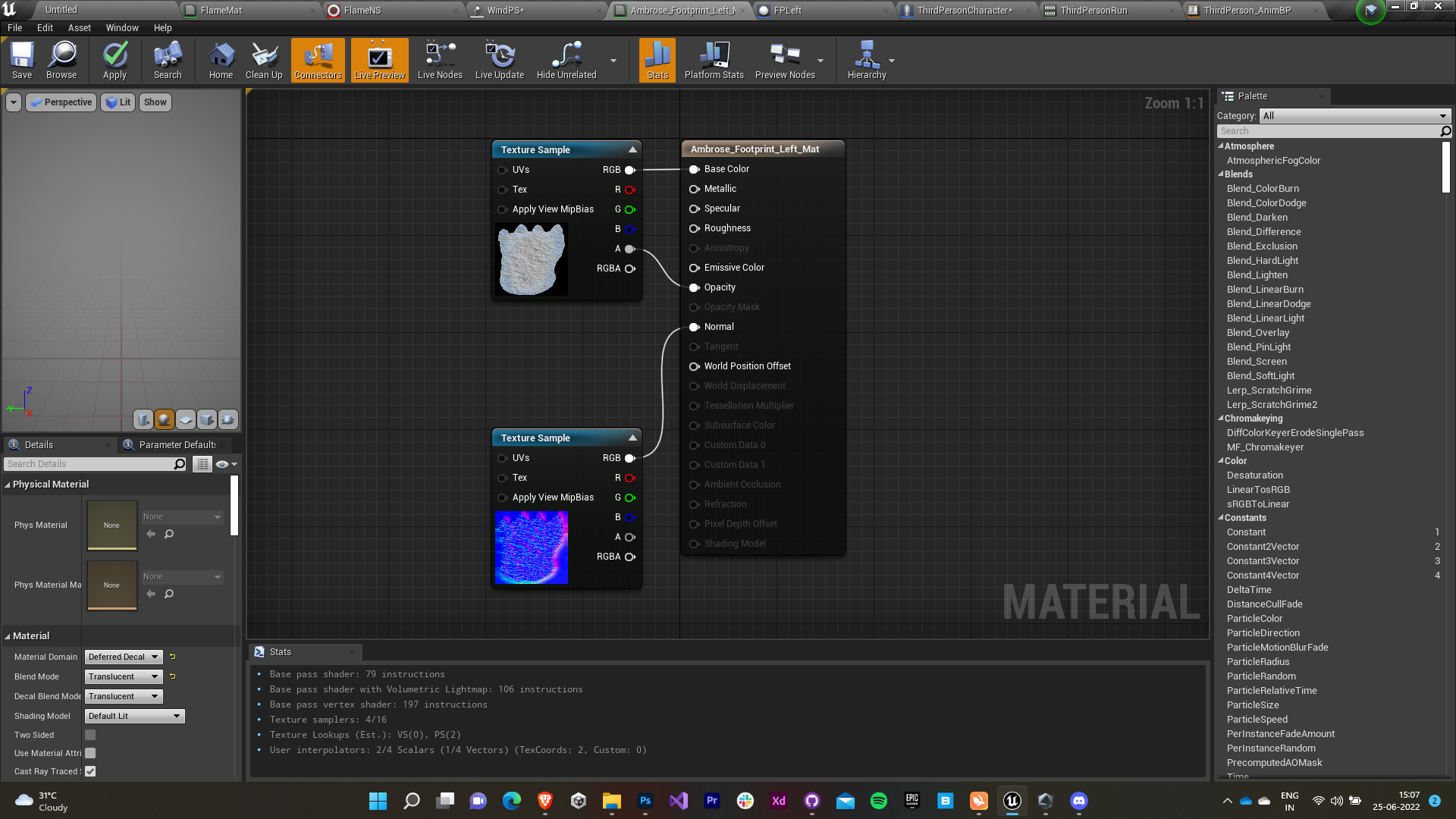
    3.7 Footprint Material - Final iteration

    The footprint material was modified to support normal information and the normal map textures generated were assigned.


    Final Output

    4.0 Snowstorm System

    My next task was to design and develop a snowstorm system for the yard area. I was provided with a reference video for the same.

    4.1 Snow Particles

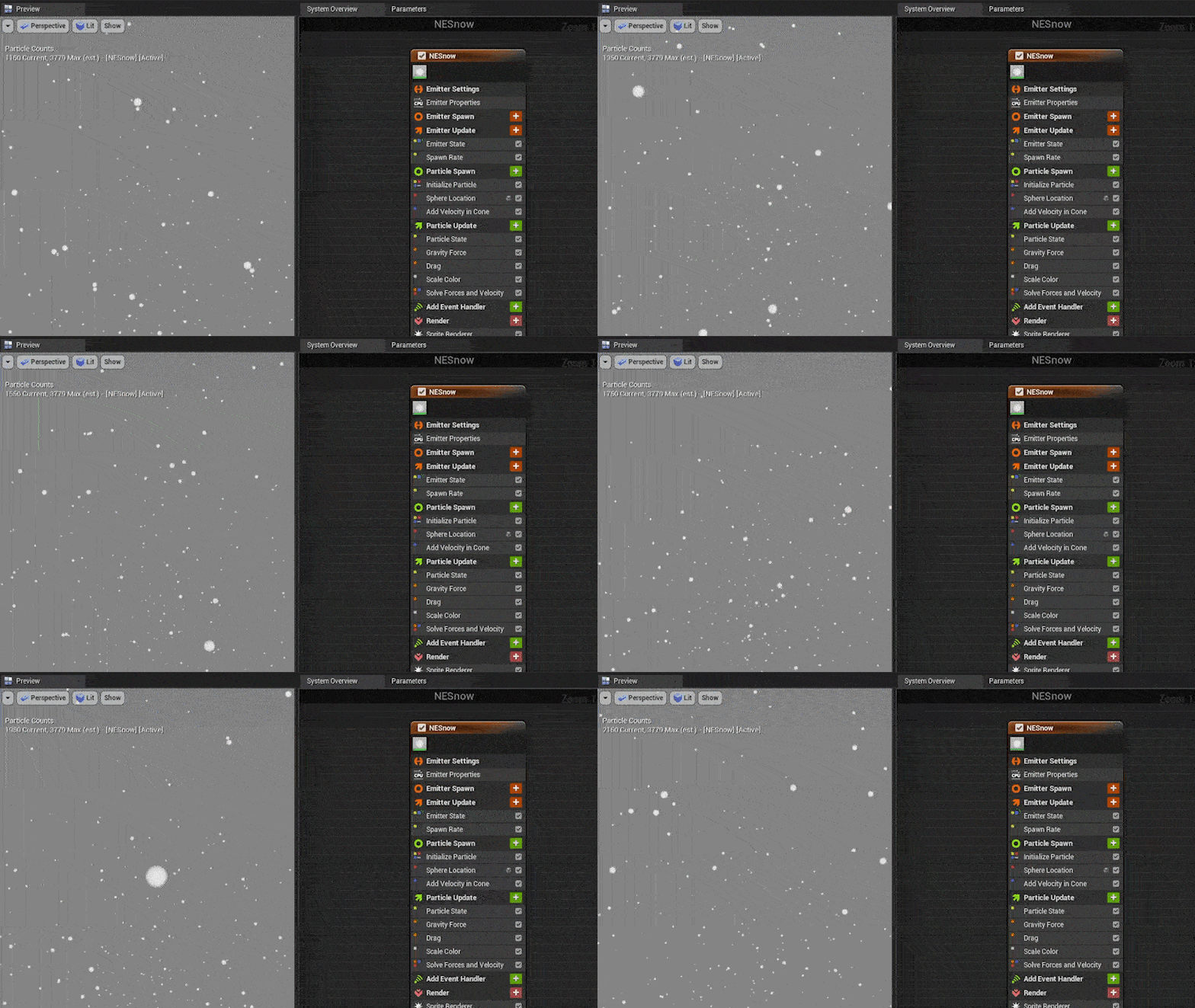
    • I found this task quite easy and felt that simply a fountain emitter with the default particle renderer would do the trick.
    • So, I created a fountain emitter and inverted its initial velocity to make the particles fall downwards instead of upwards.
    • The particles were made to spawn around a big sphere.
    • The trajectory cone’s apex angle was increased as well to increase the spread of the particles.
    • The gravity was decreased and drag was increased to make the snowfall appear more genuine.

    4.2 Wind Material

      As I had anticipated, I was suggested to add more depth to the snowstorm. The idea was to make the snow more dramatic by introducing a wind system. They provided a reference video as well.
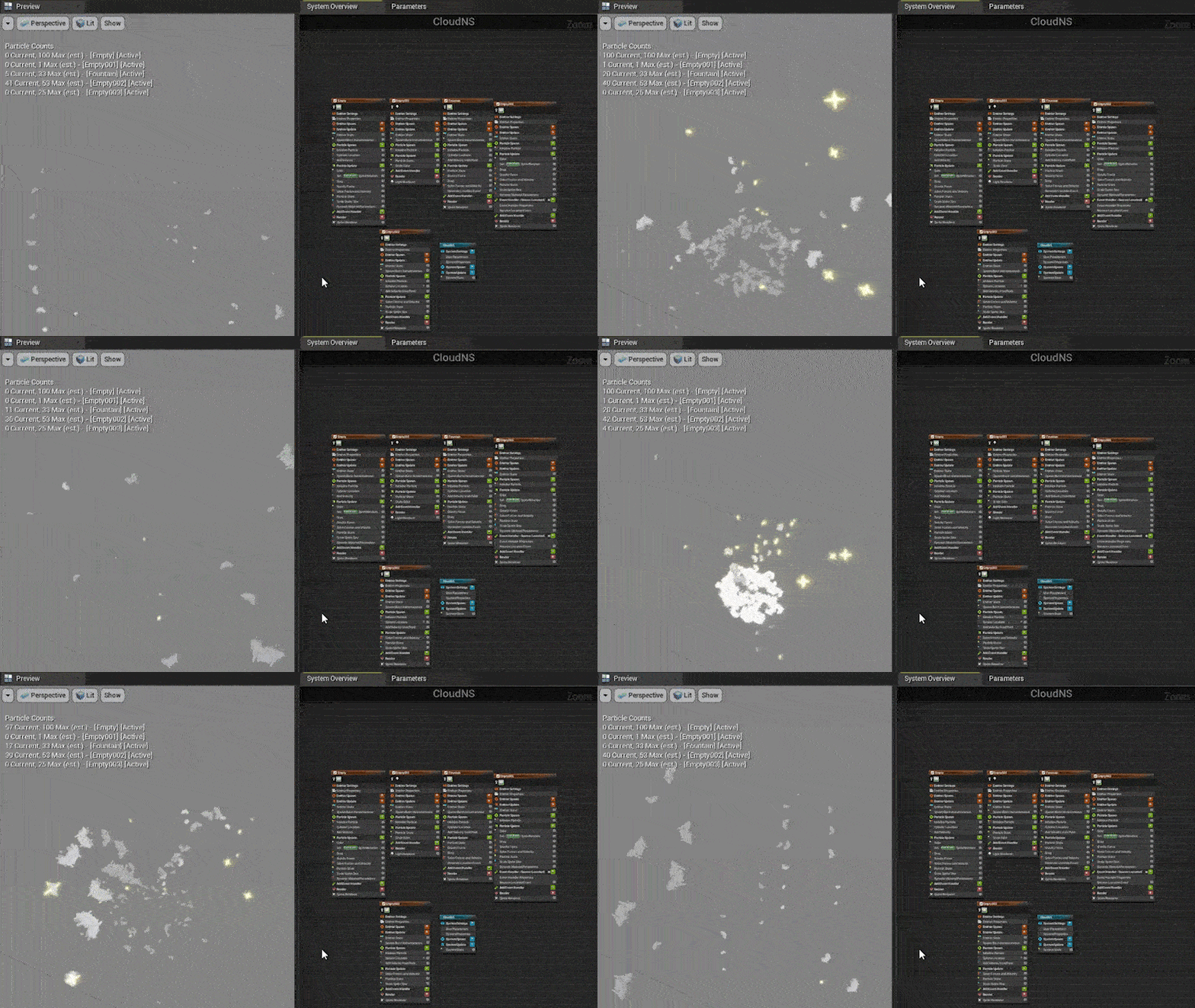
      • A translucent unlit material was chosen for the wind particles.
      • The emissive color was made to be driven by the particle color.
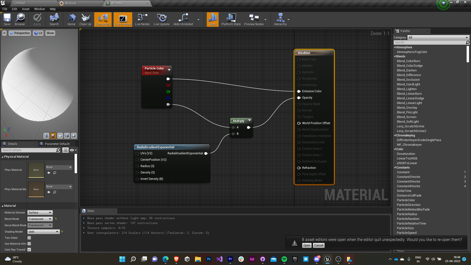
      • The opacity was controlled by the multiplication of the alpha value of the particle with a RadialGradientExponential to introduce a smooth gradient fall-off that would make the wind look natural.


      4.3 Wind Particles

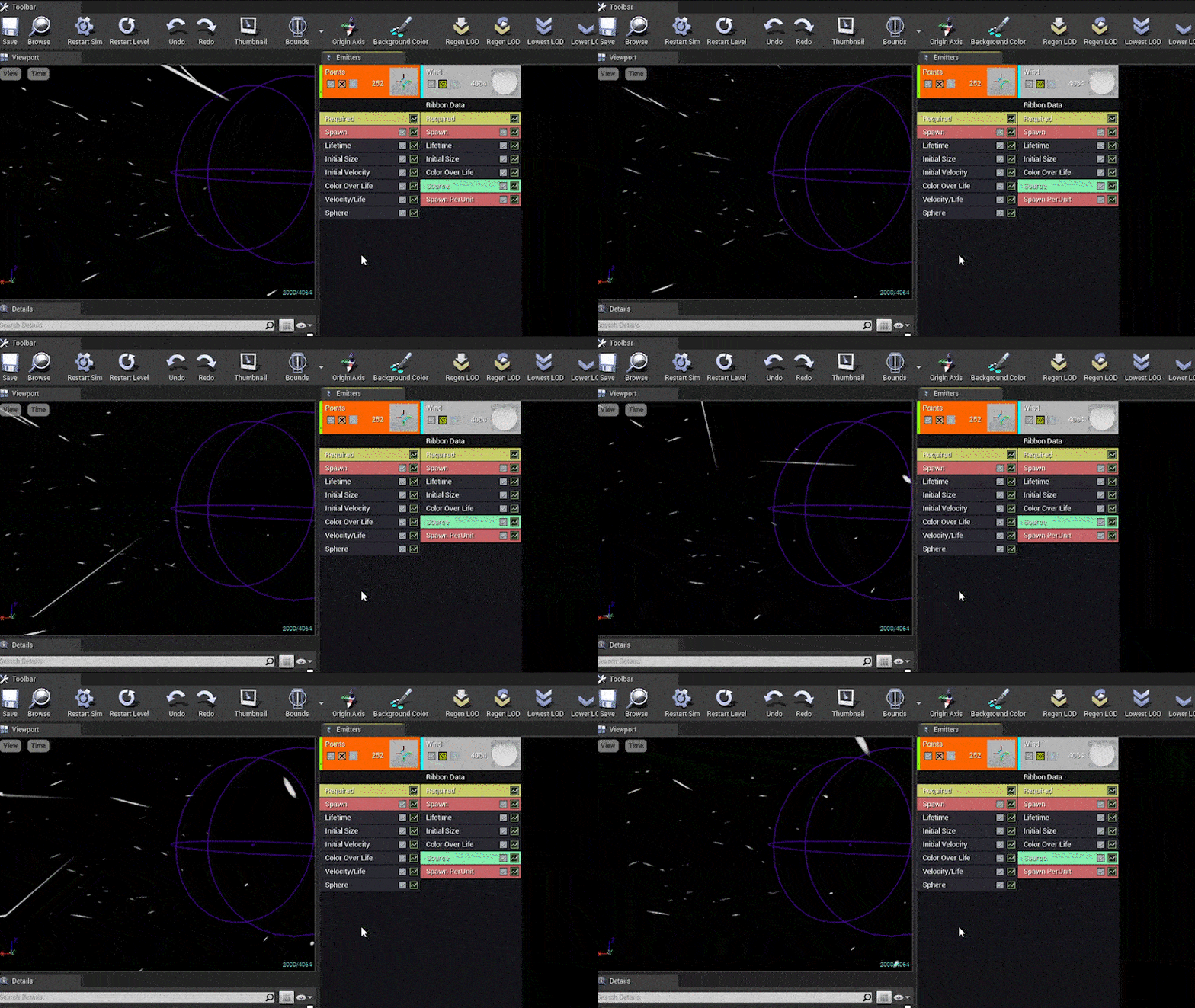
      • A new Cascade particle system is created and the rendering for the default emitter is turned off.
      • The particle is given random horizontal velocity with minor deviations in other directions.
      • An emitter for trails is added and it’s made to follow the first emitter and spawn alongside it.
      • The wind material created earlier is added to the trail emitter.
      • The scale is made to represent a long trail.
      • The direction of velocity is made to ribbon over its lifetime to make the trail follow a wave-like pattern.
      • The particles are made to spawn around a sphere with controllable radius to control the spread.


      4.4 Fog Texture

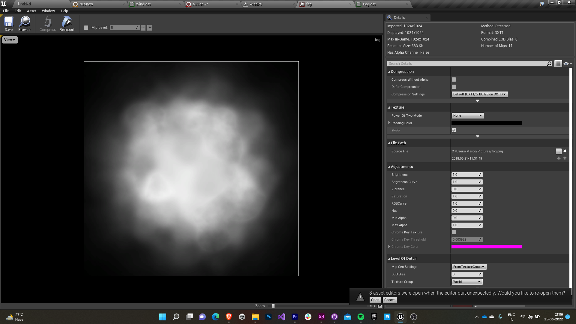
      A smooth noise texture (obtained online) was used as the fog texture for smooth light absorption (extinction).


      4.5 Fog Material

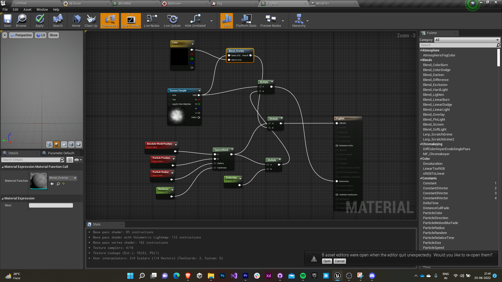
      • A volume-based material with additive blending is created for the fog to be volumetric.
      • A sphere mask between world and particle position with particle radius as the mask’s radius is used to control the rate of light absorption (extinction) of the material.
      • The mask is parametrically controlled by a hardness and extinction value multiplied by RGB value of the texture I obtained earlier.
      • The albedo of the material takes in the mutiplication of the sphere mask and the blend overlay between our texture and a RGB value parameter which we can control in the instance of that material.
      • Thus we can control the hardness, light absorption rate and the color of the fog.


      4.6 Fog Particle

      • A new Cascade particle system is created and an instance of the fog material is assigned to it.
      • The particle is scaled only along the X-axis & Z-axis to represent a flat surface and its velocity is set to zero.
      • This particle needs to be paired with an exponential height fog (with volumetric fog enabled) to render over the screen.
      • The particles are spawned around a cylinder (having zero thickness) with its flat edge in the X-Z plane.

                 Fog Color                                 Fog Extinction & Hardness
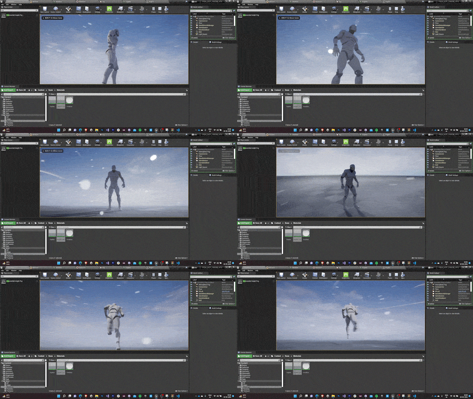
      Finally the snow niagara system, wind cascade system, fog cascade system & an exponential height fog (with volumetric fog enabled) are added into a single blueprint actor to be used in the yard scene as a snowstorm system.

      5.0 Cable system

      My next task was to come up with a physics-based cable system that was mostly to be used for cosmetic purposes in the game.

      5.1 Cable Actors

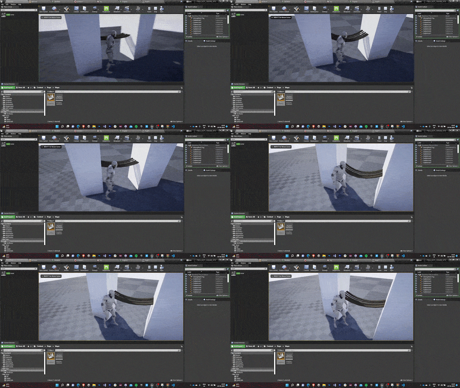
        Fortunately, Unreal comes preloaded with cable actors with rope physics for on-the-go usage.
        • These cables implement the traditional way for rope physics i.e. using a series of particles with motion constraints between them.
        • The texture maps were obtained from the Quixel Megascans.
        • The physics is constrained between objects that the cable is attached to them by using Physics constraint actor between the two objects.
        • Cable’s end is attached to any one of the objects.

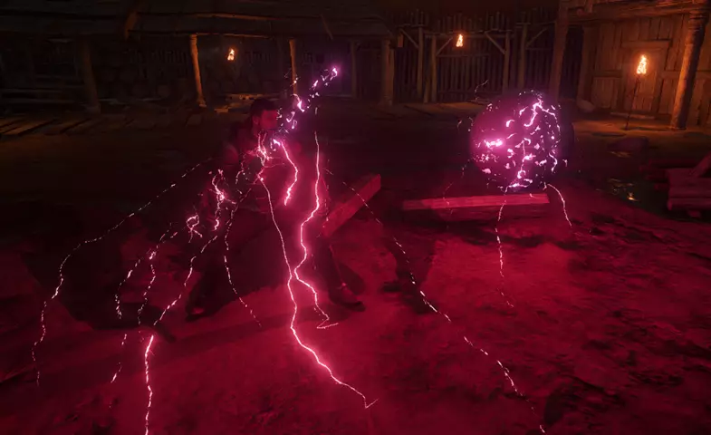
        6.0 Glowing Crack Material

        The team then assigned me the task to come up with materials with glowing cracks. They provided me with references aswell.

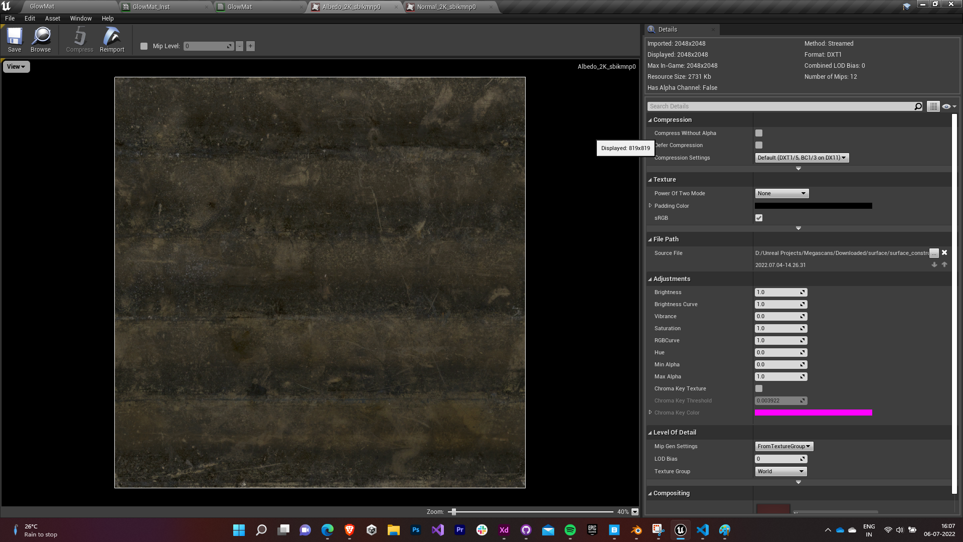
        6.1 Crack textures

        • As the reference for the material that I was provided with was a Unity asset, I tried reverse engineering the properties of the material to recreate it in Unreal.
        • I could make out that a single color channel of the base map (Albedo) was inverted and clamped between 0 and 1 and was multiplied with the emissivity input for the material.
        • The single channel input texture ensured that the light emitted took greyscale values according to the base map and we could control the intensity, rate, color tint, etc through the emissivity input.
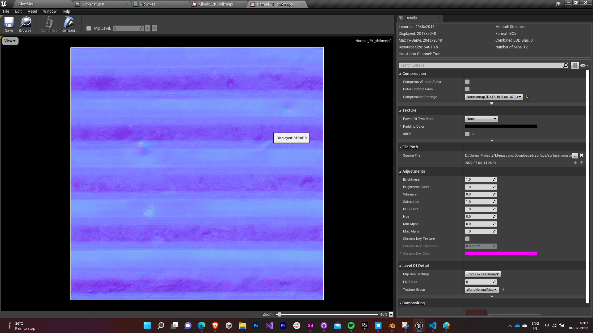
        • A normal map was also used to add depth information to the cracks to make them look more realistic.
        • So I imported a non-uniform galvanized metal’s texture maps (base & normal) from the Quixel Bridge for this purpose.

        Base Map                                         Normal Map

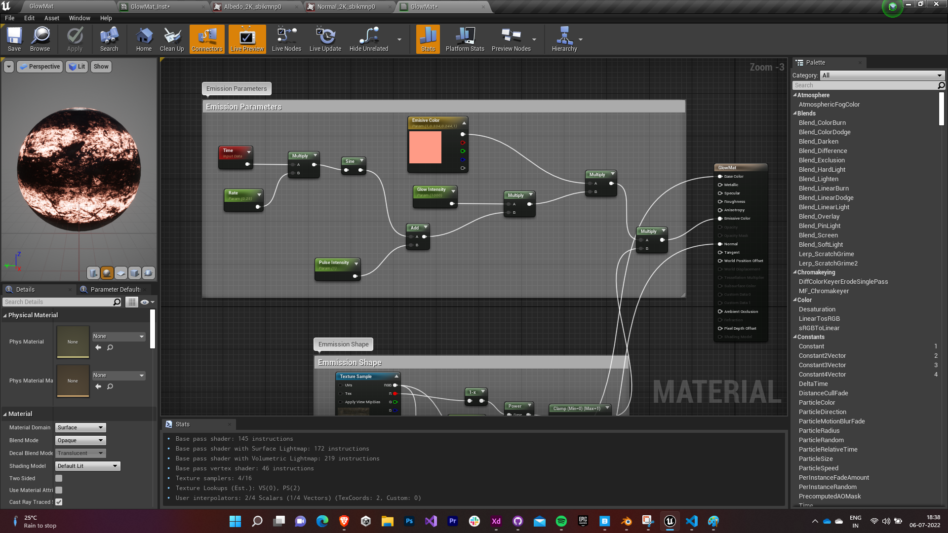
        6.2 Emission Parameters

        • The emissive color parameter of the material is governed by a time-dependent sine wave that leads to pulsating behavior by the glowing cracks.
        • The sine input is given a Rate factor as its frequency, to control the rate of pulsation.
        • Then the wave is given an offset governed by the Pulse Intensity. Its value is preferably kept to be greater than one to avoid negative waves (this prevents lag between the pulse cycles).
        • The offseted wave function is amplified by a Glow Intensity factor to control the amplitude of the glow.
        • Finally the entire amplified function is multiplied by an Emissive Color Vector parameter which governs the color of the glow.
        • The Rate, Pulse Intensity, Glow Intensity, Emissive Color are parametrically exposed to be controlled by the instance of that material.

        6.3 Emission Shape

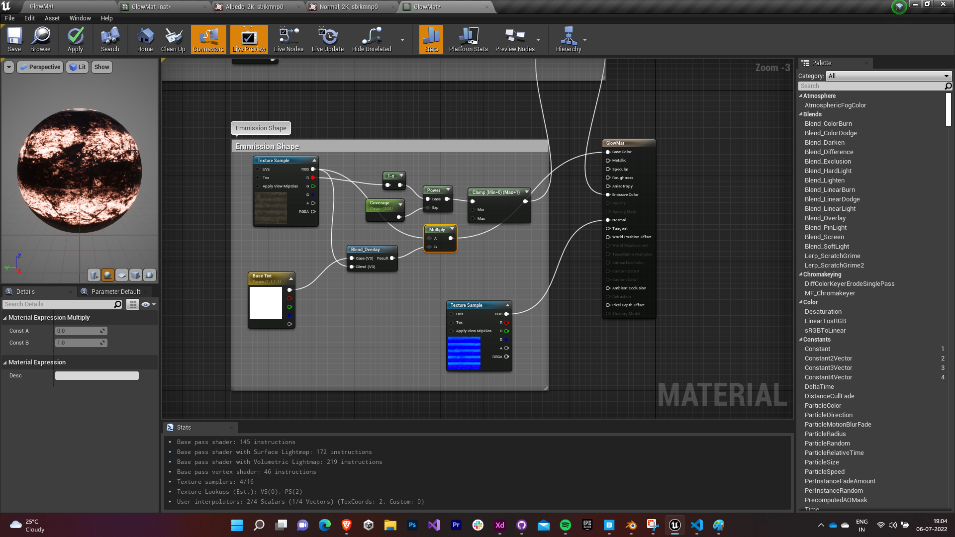
        • The base color of the material is governed by the base map of texture and a Base Tint Vector factor.
        • The base map is blend overlayed with the Base Tint as the base. This ensures that whenever the blend is greater than half the grey value, it will get screened else it will get multiplied. (Every blend option was tried and the Overlay type was found to be best suited for our purpose).
        • The final blend output is multiplied again with the base map and assigned to the base color of the material.
        • The normal map is assigned as the material’s normal as it is.
        • The shape of the emission is governed by a single color channel of the base map (all three were tried and the Red channel felt the most appealing to the eyes).
        • The color input is inverted using 1-x node and it is assigned a Coverage parameter as the exponent.
        • The value is clamped between 0 and 1 and is multiplied by amplified function obtained above and finally assigned to the emissive color property of the material.
        • The Base Tint & Coverage are parametrically exposed to be controlled by the instance of that material.


        A material instance of this material was created and assigned to one of the items in the game.

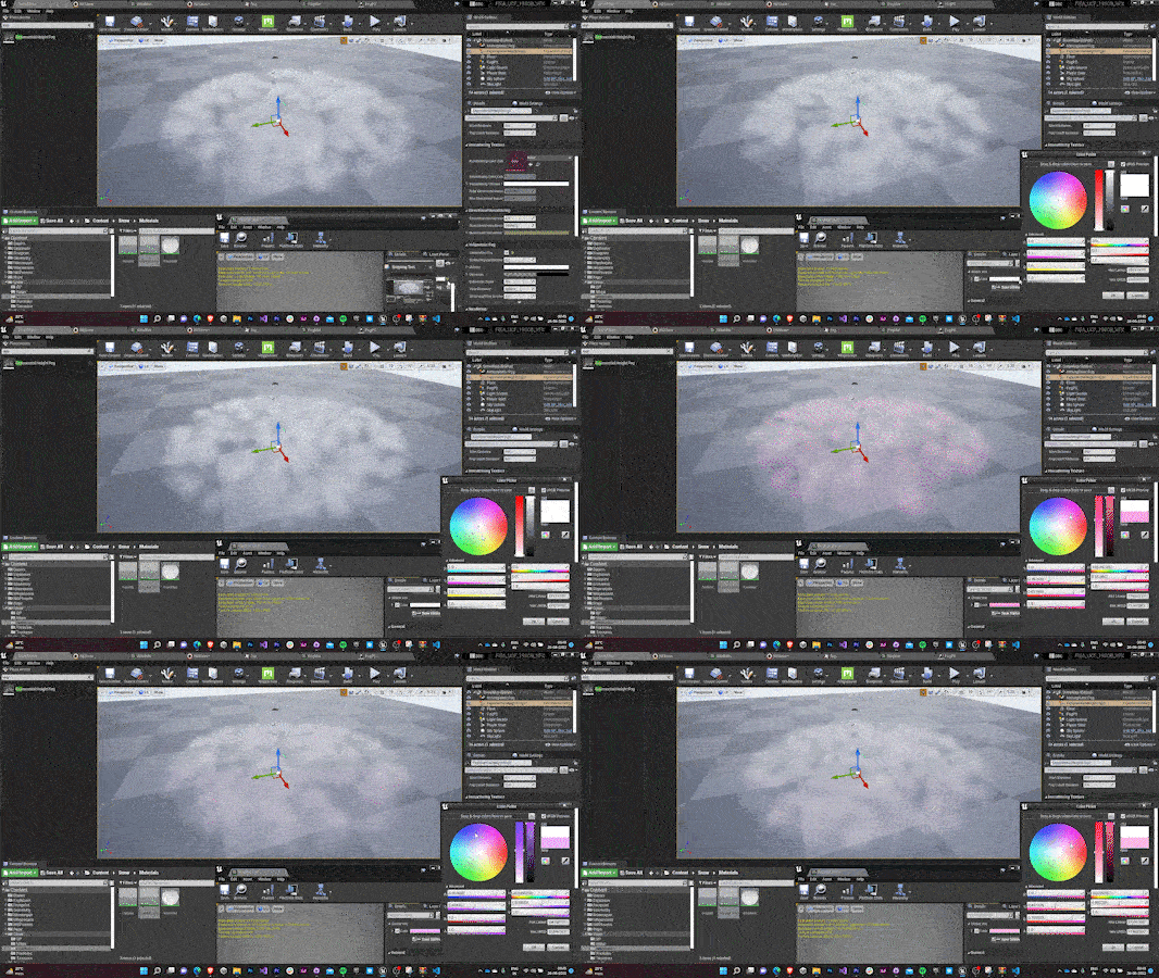
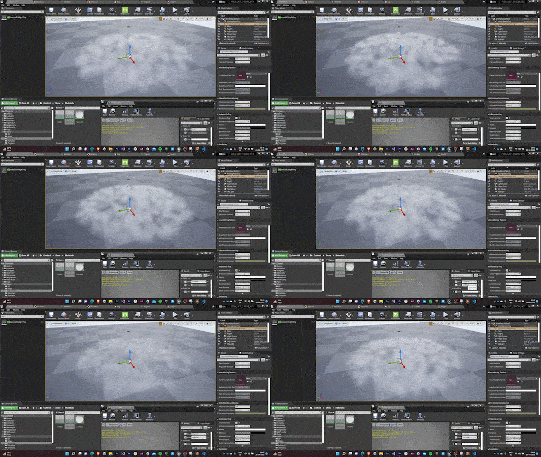
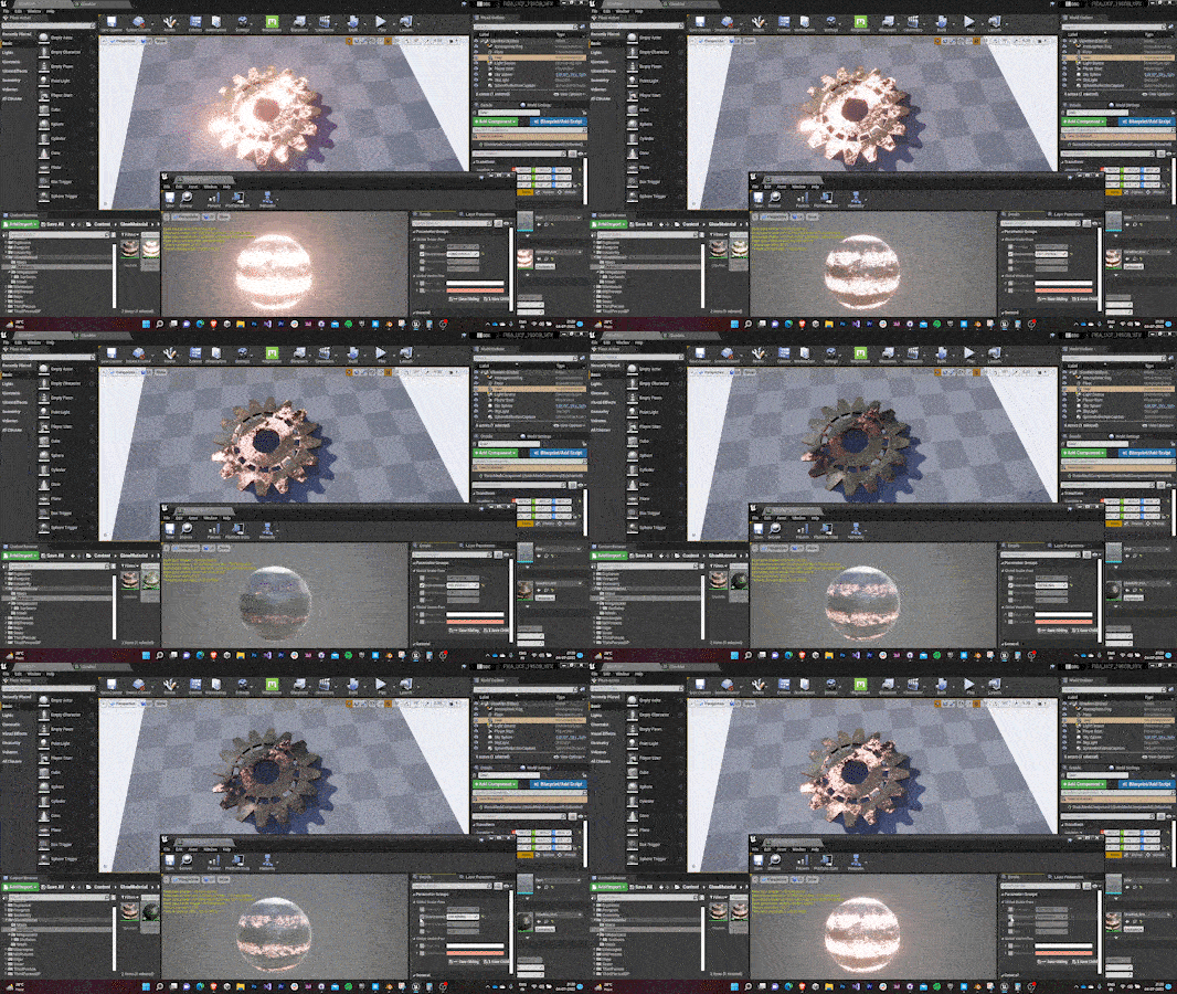
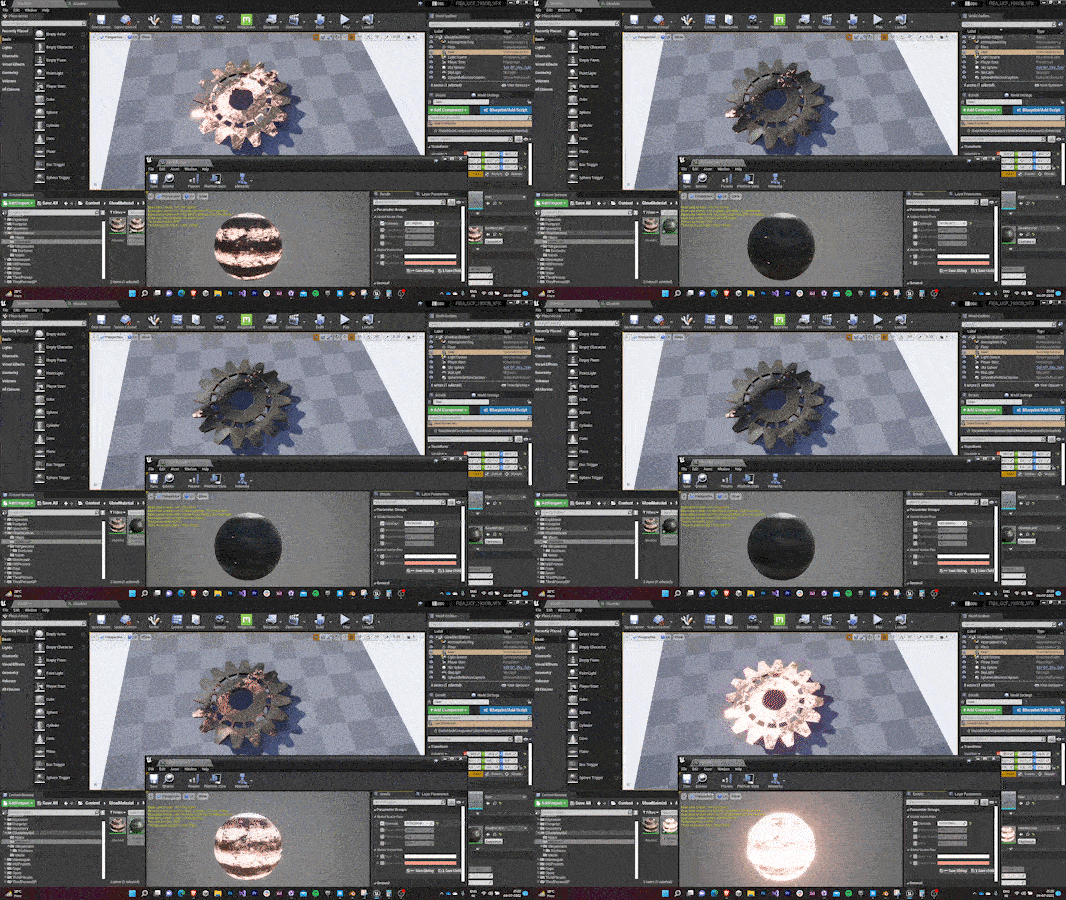
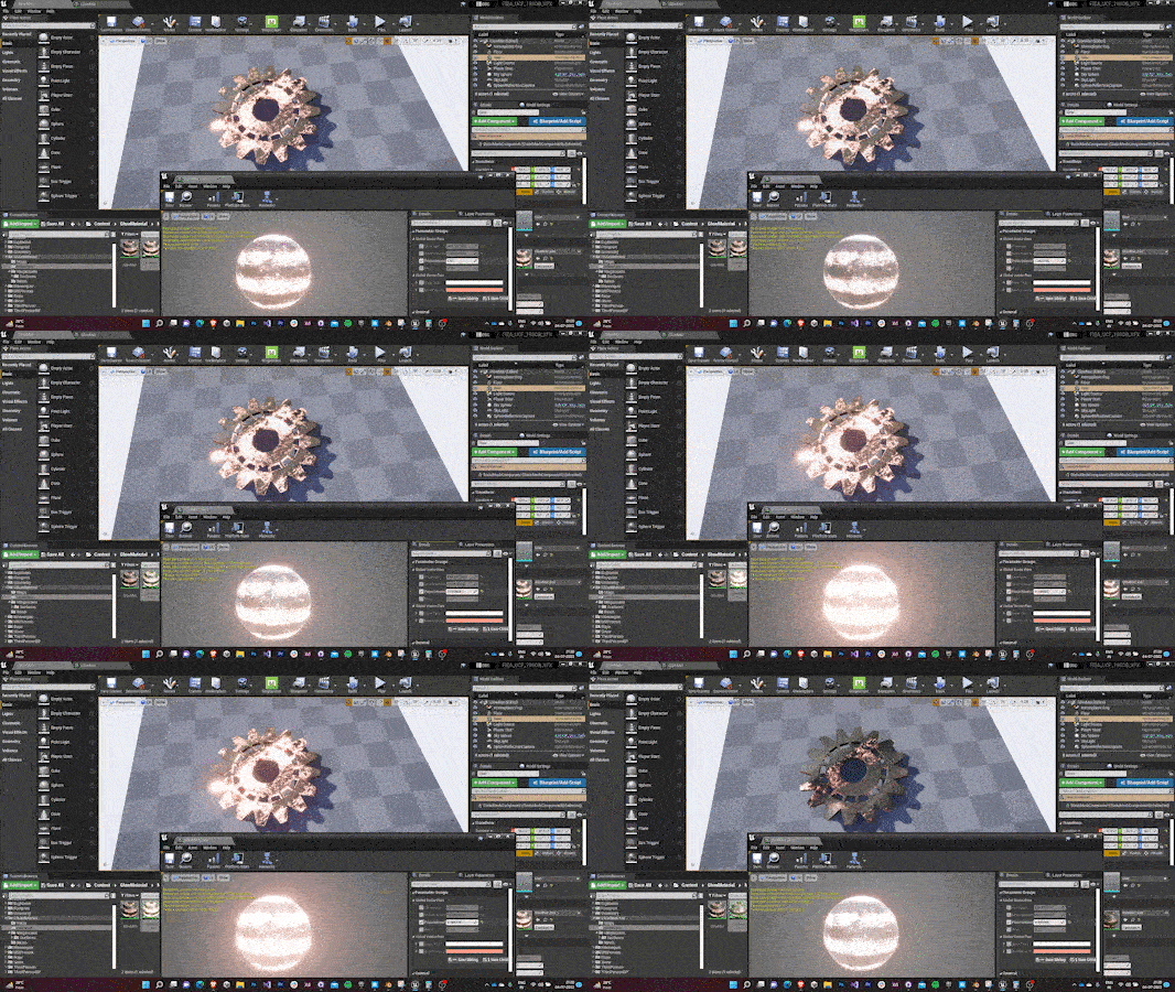
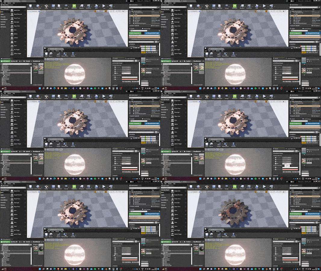
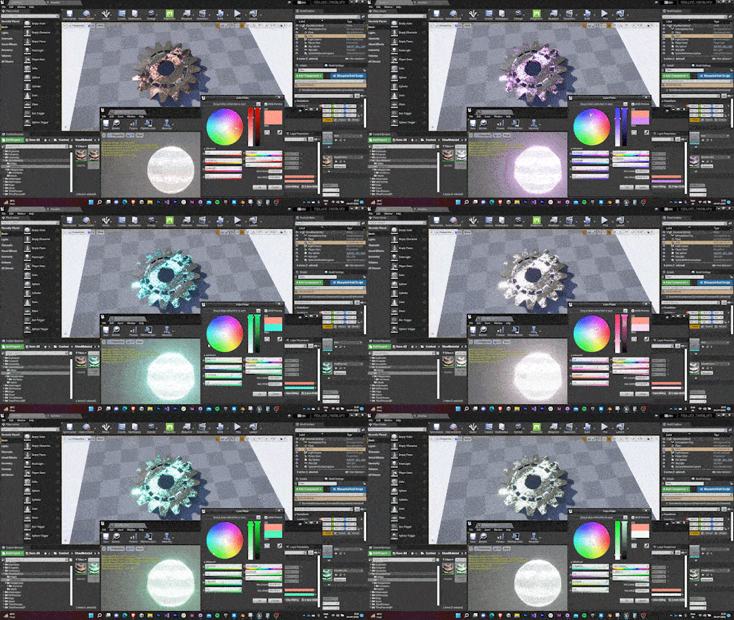
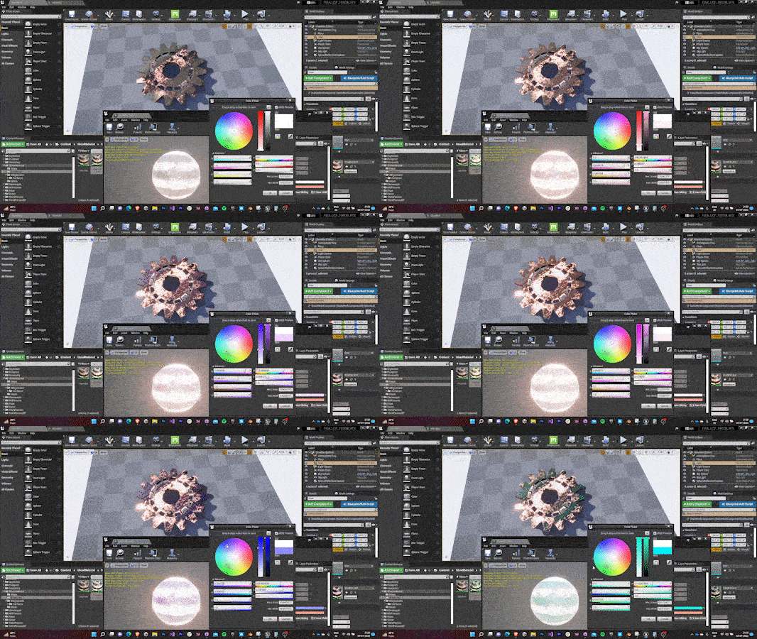
        Changing Glow Intensity                      Changing Coverage
        Changing Pulse Intensity                             Changing Rate
        Changing Emissive Color                      Changing Base Tint

        7.0 Loading Screen

          I decided to switch my role to explore the track of a tech designer. I was assigned the task to design a loading screen for the various scene transitions in the game.

          7.0 Widget

          • A 16:9 widget was created to serve as the lock screen.
          • A video was provided to be used as the background for the lock screen.
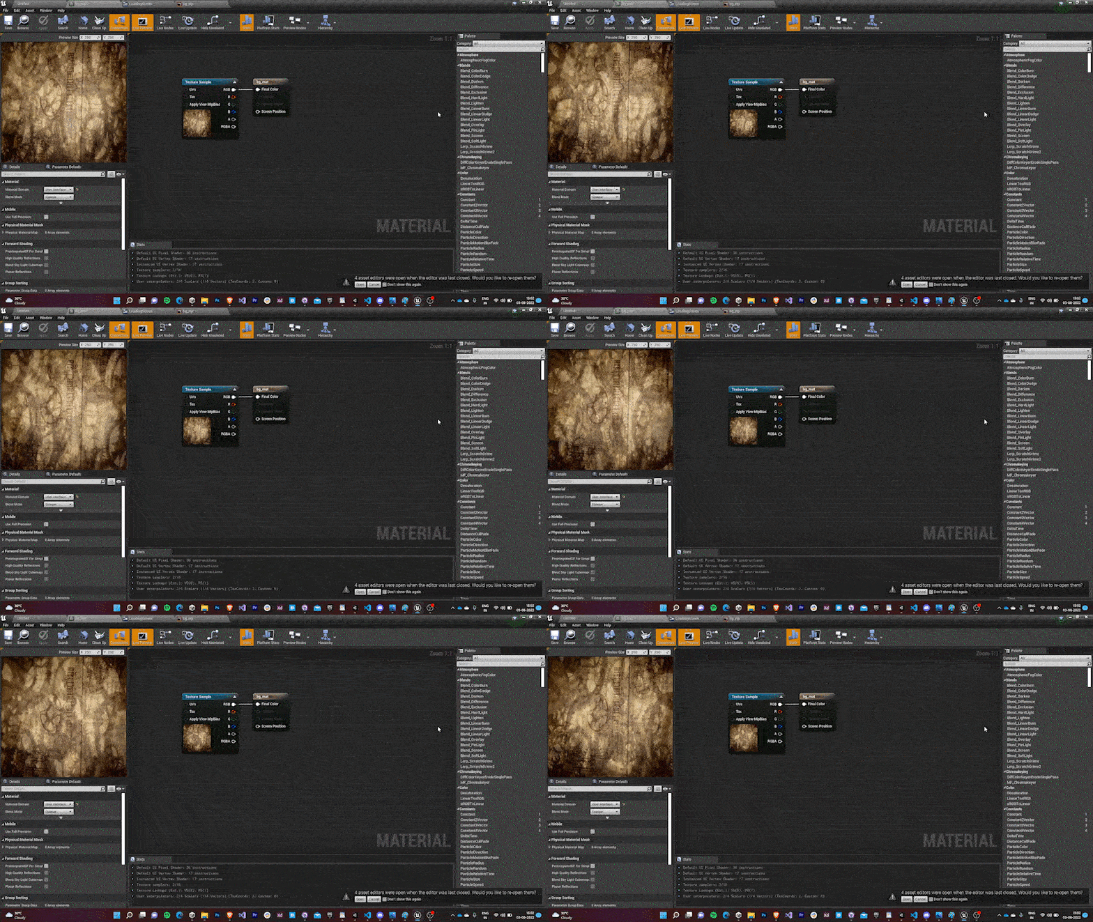
          • Since Unreal Engine doesn’t support Video files for Widget as is, I had to do a walkaround. I imported the video as a media player and created a video texture out of it. Then I created a material with UI domain that could be used in the widget as an Image. (Image in widgets support the use of materials as a brush)
          • The video was looped and precached to avoid any frame drops in between each loop.
          • The default Rendering Hardware Interface was changed to DirectX11 as Vulkan/DirectX12 eventually failed to cache the video and led to a black screen.

          7.1 Progress Bar

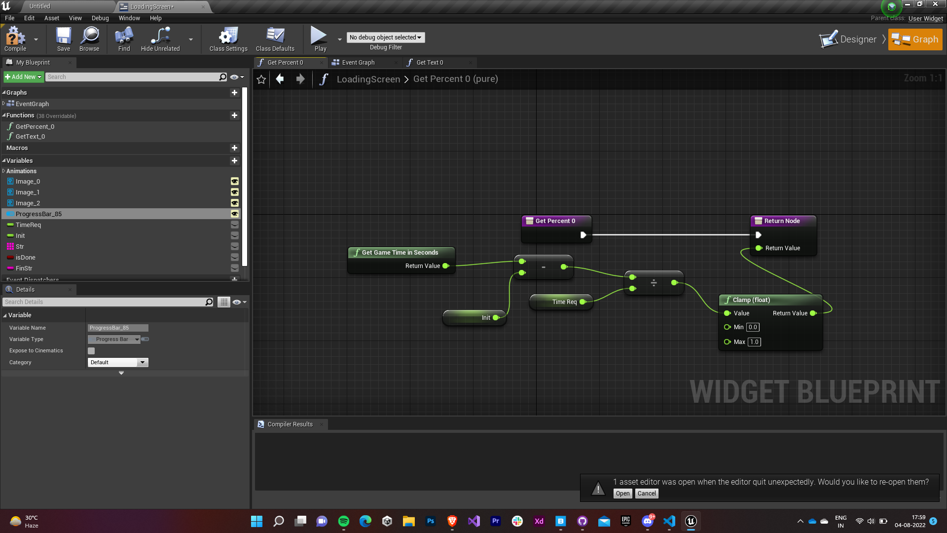
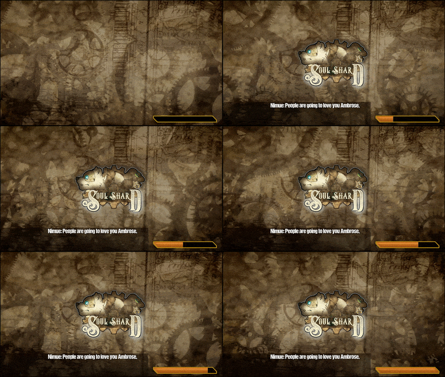
            The team wanted me to implement a progress bar whose colors can be controlled by us in the engine. Apart from this the progress bar’s progress was to be linked with the amount of level content and lighting information was loaded in the level.
            • I used the Progress Bar prefab provided by the Unreal Engine in the Widget Palette as the base.
            • The progress percentage was bound with the GetAsyncLoadPercentage with an upper clamp on the timing.
            • A custom sprite was used for the progress bar aswell.

            7.2 Tips System

              Next we decided upon implementing a tips system that would show up random tips on the widget while the level is loading. 
              • A semi transparent black box was used as the container for the textbox of the tips that would come randomly.
              • DCC font was used for the text to keep it seamless with the game.
              • The text was randomly chosen from an array of strings and was set to switch to another string after a threshold time.
              • The sound designers even went on to implement a narration system that read out the tips that came out on the screen.

              7.3 Widget & Level Blueprint

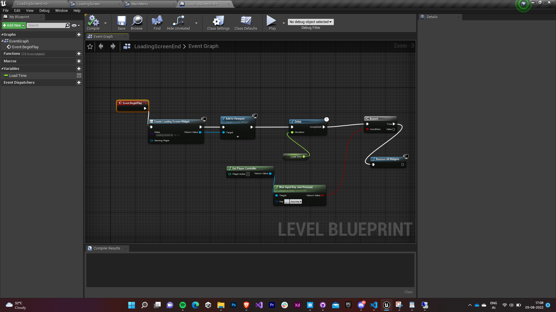
              • The widget was added to the viewport of the screen when a new level was opened.
              • It was made to wait for GetAsyncLoadPercentage to get to 100 and then a prompt was shown to press any key (cross-platform) to disable the widget and open the newly loaded level. The blueprint was made to wait for a threshold time in case the level took too long to load.
              7.4 Final Touches

              • All the widgets and elements were animated To give a more professional look.
              • The game’s logo was added in the center and was made to fade into a text prompt that asked the players to press a key to continue once the level had been loaded.

              Popuular Posts